ANTIQUE REGENERATIVE RECEIVER 1V1
In December, 2003 I described a transistor regenerative receiver for the 20 m band.
With this receiver I thought of having reached the best possible results with autodyne. Not having made any more tube receivers since the 80s, I wondered if it was possible to obtain so good results with tubes. I then dashed the challenge to build a receiver that would have been able to be realized in 1939 or 1940 by an amateur having my current knowledge. The results exceeded the expectations. Regrettably during the realization of this receiver, F9ZS a radio ham having participated actively in the training of the radio hams of the region of Lille during half a century died. I dedicate him this receiver.
The choice of the schematic was simple: it was to reproduce with tubes the receiver made with transistors. Here are the main characteristics at the origin of the exceptional results of this receiver: RF stage with aperiodic input on the emetter (cathode), tuner made with 2 coils without coupling, weak self / capacity ratio, important AF amplification with the minimum of noise to obtain a good sound level. For the tube receiver three ranges are foreseen: 20 40 and 80 metres.
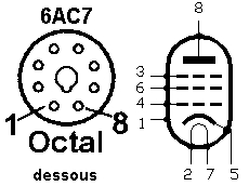
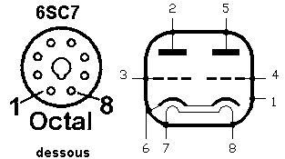
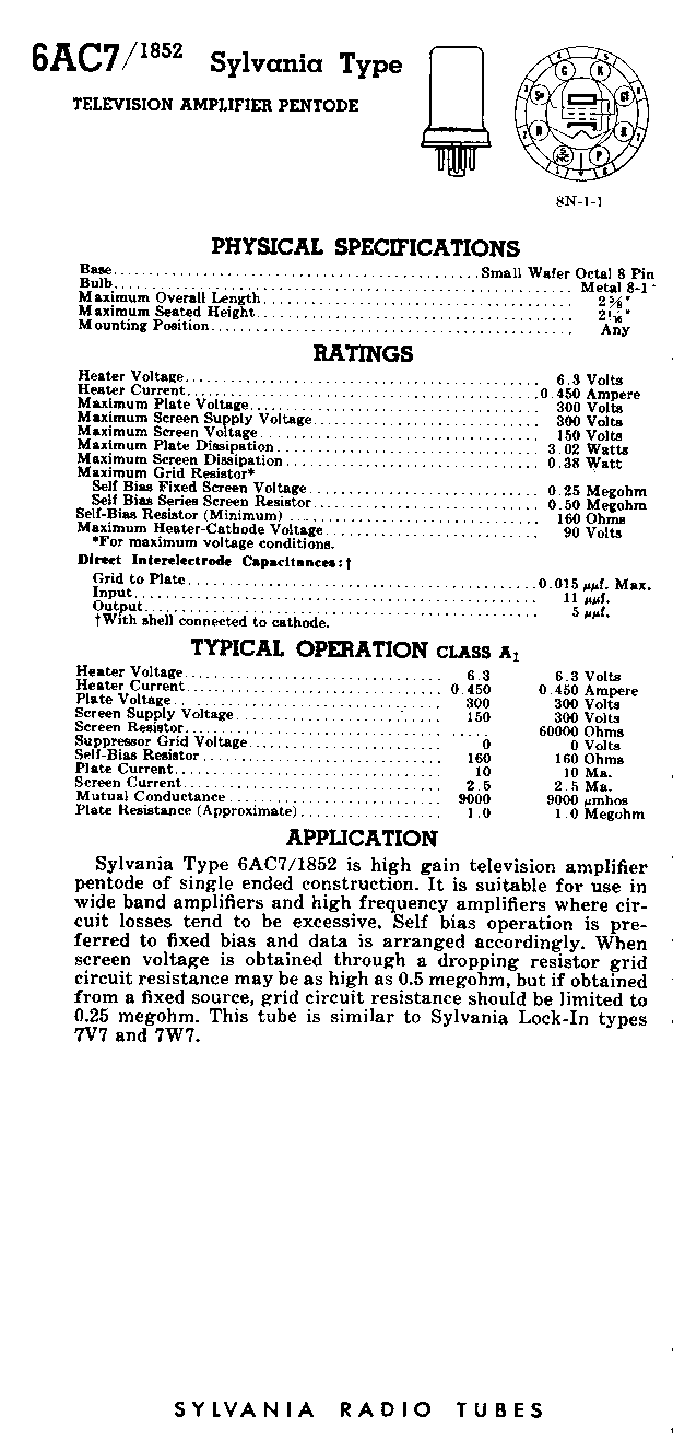
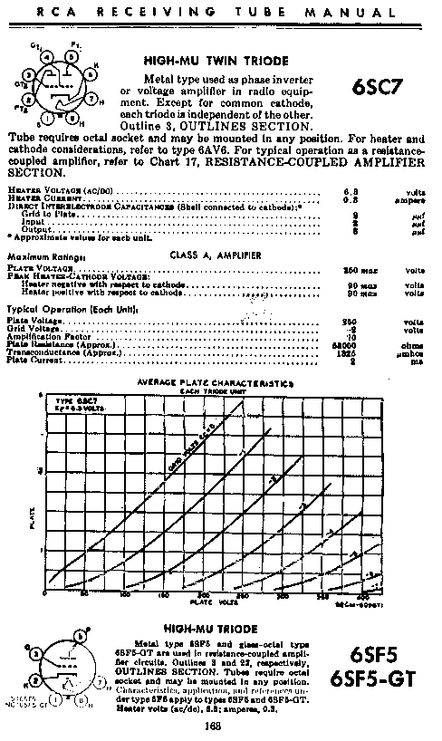
The choice of tubes was more difficult. I wanted to use only new materials. The octal series was deliberately selected because it is about the wide-spread series of tubes. In this series 2 particular tubes were chosen: RF stage and detector 6ac7 (or 1852), AF stages 6sc7. The 6ac7 is a tube with strong slope created for the first televisions to obtain a real gain in bottoms of the VHF ( 30 60 Mhz). The tube was already present in the 1939 handbook of the ARRL. The 6sc7 is a twin triode specially conceived for the AF. The tube was used in 1941 by Hallicrafters (Rx model SX-28). The characteristics of these tubes are easy to find on the web. The noval equivalences are EF183, EF184, EF80 for the RF tube and ECC83 for the twin triode.
The shematic is given figure 1. The input ot the RF tube is the cathode, what gives a good linearity in spite of the aperiodic assembly and an exceptional isolation between the antenna and the oscillating circuit. There is thus, no interaction between the RF gain and the detector. The RF tube is coupled to the cathode of the detector tube. The resistance of detection (1 Megohm) is connected with a slightly positive tension what facilitates the oscillation on 20 m. The AF amplifier is classic, the output transformer is a common supply transformer 5W 240V / 6V. All the capacitys in connection with the anodes or high tension must be at least 250V.
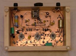
The band switching (figure 2) is extremely simple. Two series of 3 miniature switches choose the circuit of cathode and of the first screen. To change the band, it is necessary to put back in rest position 2 switches of the range to which is adjusted the receiver then to put in working position 2 switches of the wished band. The use of elementary switches allows to realize easily the circuits of switching without extending the connections.
The resonant circuit is the critical part of the receiver. Coils are made with 0,2 mm2 section wire (diameter of 0.5 mm). You should not decrease the diameter of the wire. They are made on the body of a pen ball-point being 8 mm in diameter, except L2 for 80 m. The output connections are twined on 2 tours to stiffen reels. The coils are then removed from the ball-point. Once the receiver finished turns are stick with cyanocrylate glue. it does not have a coupling between L1 and L2 (4 cms at least). VHF Shock are necesaty to avoid interferencde from FM broadcast transmitters. It is necessarily to respect NPO capacity to obtain a good frequency stability. The variable capacity is a 4 cages AM / FM. It has to be of excellent quality. A FM cage is used on all the ranges. The second FM cage is used for 40 m, and an AM cage AM is used on 80 m.
Values of coils (diameter 8 mm):
L1 4 turns (20m, 5 turns (40m, 9 turns (80m.
L2 5 turns (20m, 10 turns (40m, 14 turns (80m, on tube plastic tube 14 mm in diameter).
VHF shock 10 turns.
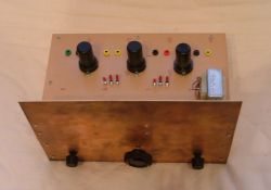
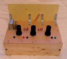
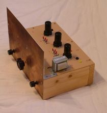
The receiver is assembled on 2 copper bakelite boards assembled in frame "chair" (30 x 20 cm). The horizontal board is put, the copper downward, on a wooden U. The second board serves as the front face. It is fixed directly to the U , but also in 2 places (approximately 1/3 2/3) to the horizontal board by set squares to obtain the best possible rigidity. Resistances of 10 Megohm 1 / 4W (or 4,7 Megohm) are used as isolated borders of connection! Their resistance is so raised that it can be considered as infinite in this receiver. The use of ceramic supports for the tubes is highly advised.
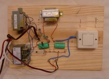
The power supply (figure 3) is obtained with a transformer of isolation 230 / 115-115 (30VA) followed by 2 diodes 1N4007 and a cell of filtering consisting of 2 x 47µF capacity and a secondary of a transformer 230 / 48 (10VA). We obtain 170V. The low voltage is obtained by a simple transformer 230 / 6. Its power has to be of at least 16VA. Notice the 330 ohm resistances.
What are the results of this receiver? Unexpected! The association of an original schematic for the RF amplifier, excellent quality component and a reasoned realization gives an exceptional quality for a 3 tube receiver. After 15 minutes of preheater it is possible to listen to a SSB station on 20 m during more than a quarter of an hour without retouching the frequency. It is possible almost always to listen to 40 m in spite of the stations of broadcasting near. I heard Australia on 14MHz and the USA on 3,79 MHz, from France.
F5LVG
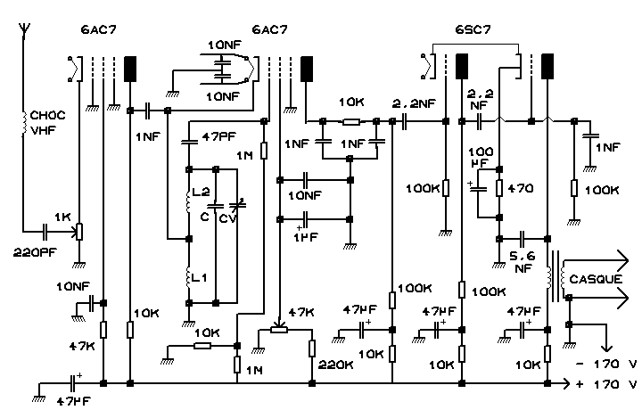
Figure 1: the receiver
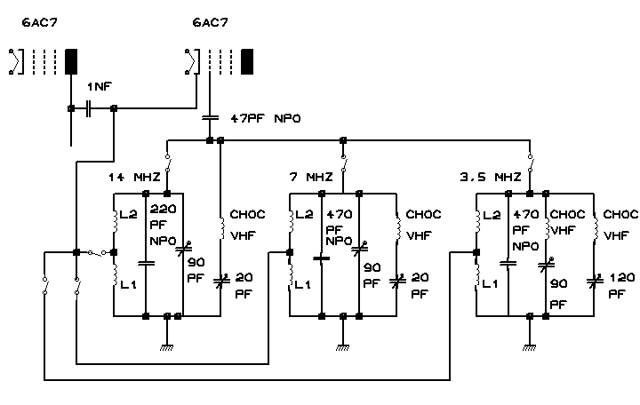
Figure 2: band switching
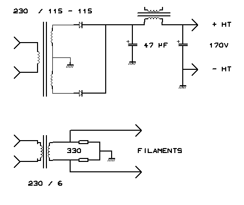
Figure 3: power supply
 .................
F5LVG
December, 2004
 ............................