Four tubes FM receiver
To react to the end of MW LW broadcasting, I set myself to build a tube FM receiver, which is as simple as possible and close to the MW LW technique. It will be a superheterodyne with 4 tubes. However, to avoid having to install an external antenna, two IF stages are essential. The first tube will be a frequency changer, the second and third will be IF amplifiers. The fourth will be both an AF pre-amplifier and a power AF amplifier.
The criteria used for the construction of this receiver are as follows:
The tubes must be easy to find on Ebay and reasonably priced. All other components are still manufactured in 2021. The use of semiconductor diodes is possible. The number of circuits to be adjusted should be as small as possible, which makes the use of ceramic filters indispensable. This is the only real anachronism. The use of shielding is reduced to a minimum. To simplify the realization, the demodulation is done by a detection type amplitude modulation on the side of the passband. There is no unique control.
The final receiver is relatively sensitive and selective: it receives all the stations received by a standard pocket receiver and perfectly separates the stations spaced of 400 kHz or more. Its real shortcoming is the envelope detector demodulation on the blank. This causes distortion, but is still acceptable with fine tuning of the oscillator frequency to get the best possible audio. The sound quality is not HIFI, but is better than the AM reception of most MW LW receivers.
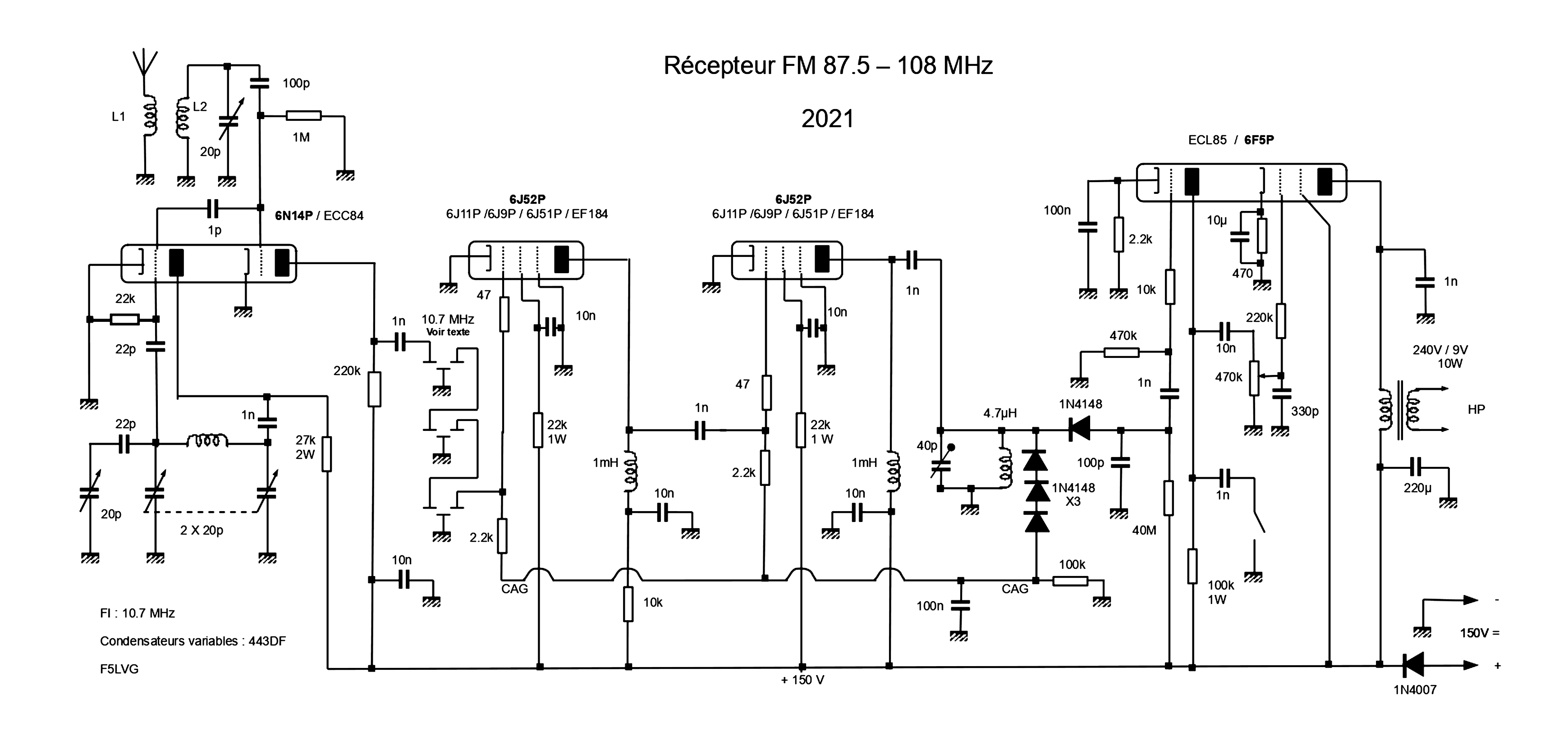
Let's look at the schematic.
The first tube is a conventional frequency changer. It uses a Colpitts oscillator tuned by the 2 20 pF sections of a 443DF variable capacitor. A second capacitor using a single 20pF section in series with a 22 pF capacitor serves as a vernier. This vernier could be removed if you use a variable capacitor with demultiplication. The mixer is loaded by a 47 kohm anode resistor which allows to directly drive a ceramic filter without intermediate resonant circuit. The value of the resistor should not be reduced, because of the possible appearance of self-oscillations. The chosen tube is a 6N14P (ECC84) which proved to be a remarkable frequency changer. However, it presents a particularity to know. This tube was designed as a cascode amplifier at 220 MHz. There is a screen, between the 2 triodes, connected to the grid of the second triode. Therefore, there is a capacitance of 1.2 pF between the grid of triode 2 (pins 1-2-3) and the anode of triode 1 (pins 6-7-8-9) while the capacitance between the grid of triode 1 and the anode of triode 2 is 0.006 pF. The 1 pF capacitor between the 2 triodes is therefore useless, even deleterious, if the mixer is triode 2 while it is essential if the mixer is triode 1.
The 2 IF stages seem simple. However, it took many tests to achieve a satisfactory result with ceramic filters. Multiple tests have shown that it is necessary to use a single filter giving almost all the selectivity of the receiver placed just after the frequency converter. The IF chain following the filter must be broadband to the detector. In practice, the filter is composed of three elementary ceramic filters in series, the selectivity provided by a single ceramic filter being insufficient. The bandwidth of the ceramic filters is critical. Their bandwidth must be 280 kHz, which is easily found on the internet (LT10.7MA5 or SFE10.7ML). Finally, ceramic filters must be loaded with an impedance close to the kohm. The 2.2 kohm output resistor is mandatory to correctly load the ceramic filters. To obtain a satisfactory gain, it is necessary to use tubes with a large slope. One of the best tubes is undoubtedly the Russian 6J52P with a slope of 55 mA/V, followed by the 6J11p (28 mA/V), the 6J9P (17.5 mA/V) and the 6J51P (EF184) (15 mA/V). The pinout calls for some comments. Some 6J52Ps have only pin 3 connected to the cathode, contrary to the official specifications where pins 1 and 3 are connected to the cathode. The 6J52P, 6J11P and 6J9P have exactly the same pinout. Finally, the 6J51P (EF184) has a similar pinout except that the connections of G2 and G3 are reversed. The 47 ohm resistors avoid VHF oscillations. The 2.2 kohm gate resistors of the pentodes avoid any risk of self-oscillation. An automatic gain control is essential to avoid saturation of the receiver on powerful stations. The series connection of 3 1N4148 diodes allows to obtain in a simple way a delay to the automatic gain control. The polarization of the 2 tubes is obtained by the grid current.
The demodulation is done by an amplitude modulation detection obtained by tuning the station on the flank of the receiver selectivity curve. The 1N4148 diode proved to be an excellent detector with a bias of 3 or 4 µA. The 40 Mohm resistor is in fact made of 4 resistors of 10 Mohm put in series. To obtain an acceptable demodulation, by this technique, it is necessary to use an adapted selectivity for the receiver. The frequency deviation in FM is + or - 75 kHz, for AF frequencies up to 15 kHz. The width of the transmission is therefore 180 kHz (75*2 + 15*2). The bandwidth of the receiver must therefore be much greater than 180 kHz. It must nevertheless remain reasonable to ensure proper selectivity. The use of 3 ceramic filters, each with a bandwidth of 280 kHz, is therefore perfectly suitable. An resonant circuit is necessary just before the detection. The choke is a miniature choke of 4.7 µH. The setting of this circuit must be very fuzzy. If it is not the case, it reflects a reaction that reduces the bandwidth and will distort the modulation. It will then be necessary to damp this resonant circuit with a resistor of a few kohms.
The AF amplifier includes only one double tube. The 6F5P tube (ECL85) has been chosen because of its great availability. However, it has a tendency to self-oscillate. This explains the 10 kohm and 220 kohm grid resistors and the 1 nF capacitor between the pentode plate and ground. The wiring of this capacitor must be extremely short. The value of the capacitors is chosen to favor the highs. A switch activating a 1 nF capacitor allows to attenuate the treble at will. A power supply transformer is used as output transformer.
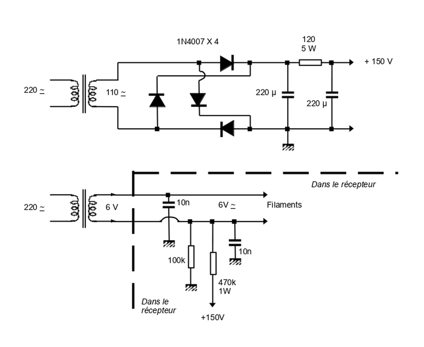
The power supply is conventional. The transformer for the high voltage is a 220 V / 110 V isolation transformer. The filaments are wired with 2 wires. A bridge divider applies a positive voltage to the filaments. With this technique used on HIFI amplifiers, the electrons released by the filament are repelled by the cathode and the control grid which appear negative. This prevents the filament circuit from inducing audio hum or frequency modulation of the oscillators. I now use this technique systematically. Otherwise, the cathode of the AF triode amplifier should be decoupled by a very high capacitance capacitor (470 µF) to shunt to ground the 50 Hz alternating current coming from the filament. The power supply is separate from the receiver, except for the resistors and capacitors of the filament circuit which are in the receiver.
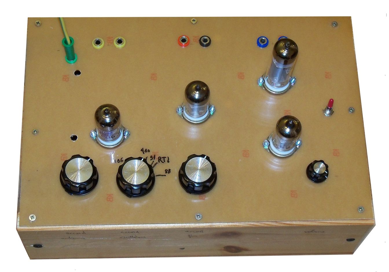
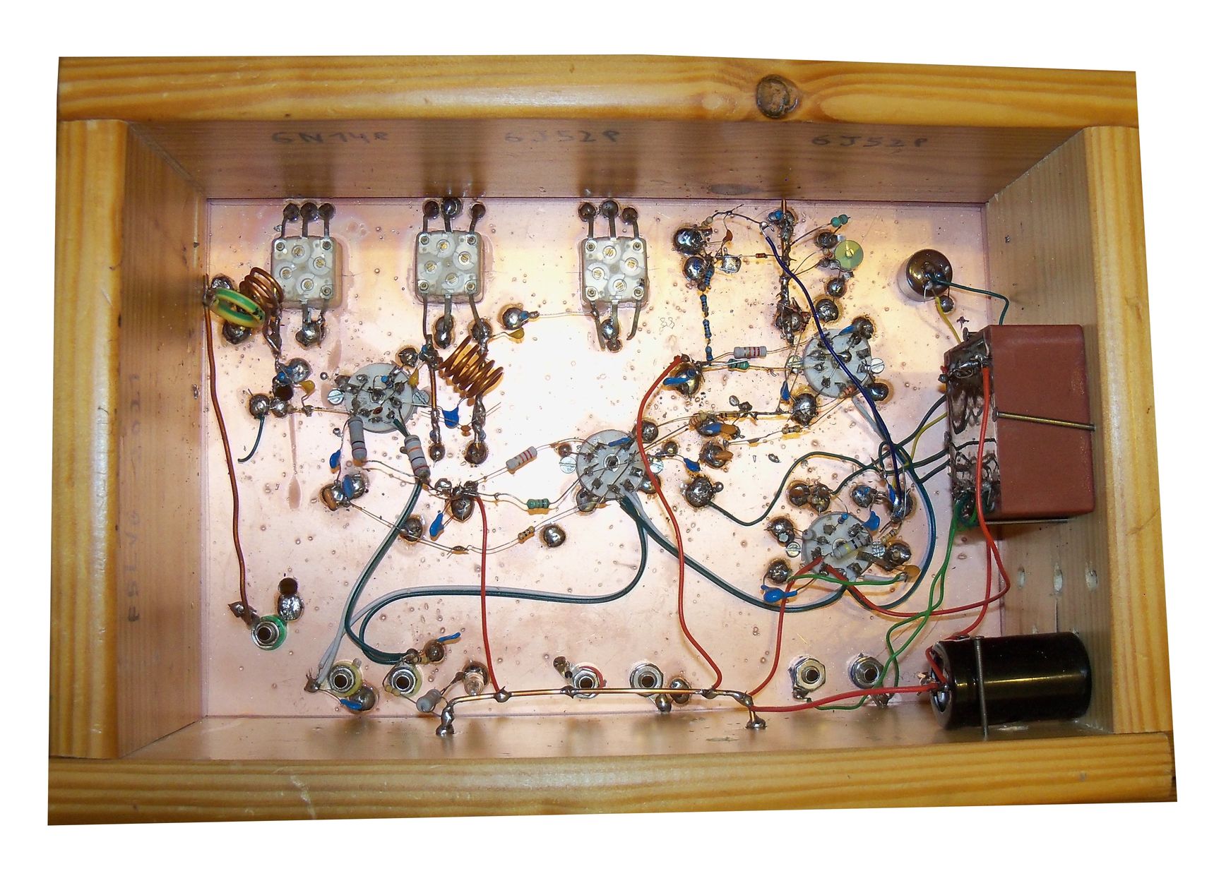
The assembly is done on a copper-plated bakelite plate of 20 X 30 cm, placed on a wooden frame, copper downwards. Resistors of 10 Mohm are used to make isolated connection points from the ground. The circuits around the frequency changer must be wired very short, like the cathode connections of the IFs. The VHF coils are made with 20 A stripped installation wire (2.5 mm²). The oscillator has 5 turns, the input oscillator circuit 3 turns and the antenna choke 1.5 turns. The diameter of the coils is 10 mm. The 3 variable capacitors (443DF) are bonded to the copper with cyanolite. The 3 ground connections as well as the 2 120 pF connections must be soldered directly to the copper plate. The antenna consists of a 20 A 40 cm wire, connected to a banana plug.
For tuning, the most difficult thing is to set the oscillator from 76.8 MHz to 97.3 MHz. If the frequency is too high, it is also possible to receive the FM band with an oscillator from 98.2 MHz to 118.7 MHz. Having the chance to have a powerful local station on 87.7 MHz, I set the 2 variable capacitors of the oscillator to the minimum capacity, then I adjust their trimmers so that this station is not audible with the upper beat. If the trimmers are insufficient, it is possible to add in parallel to the coil a small capacitor (3 pF in my case).
Build this receiver. The results are as good as it gets when you have the skill to set the exact frequency that gives the least distortion. You will find the pleasure of handling 2 capacitors to get the best possible reception and the satisfaction of being the creator of a working tube set more than a century after the development of TM tubes. It will remind you the handling of a C-119 or a BGP (see https://oernst.org/hamradio/Livres/index.html) !
F5LVG 2020