Receiver for Frequency Modulation
The goal was to realize a vintage FM receiver, built with semiconductors that were already commercialized at the end of the 70s. This receiver had to be as simple as possible, but allowing to receive with good audio quality all the stations correctly received on a standard receiver. It could therefore only be a superheterodyne.
The simplicity imposes :
- An in-air assembly, without printed circuit and SMD component.
- The use of a minimum number of resonant circuits.
- No RF stage before the frequency converter stage.
- The use of miniature variable capacitors for the oscillating circuits and not varicap diodes.
- Separate tuning for the input tuning circuit and the RF oscillator circuit.
- A simple and robust integrated circuit for the IF amplifier, the limiter stage and the demodulator stage.
- An integrated circuit in audio frequency amplifier.
- Battery powered.
- Easily available components.
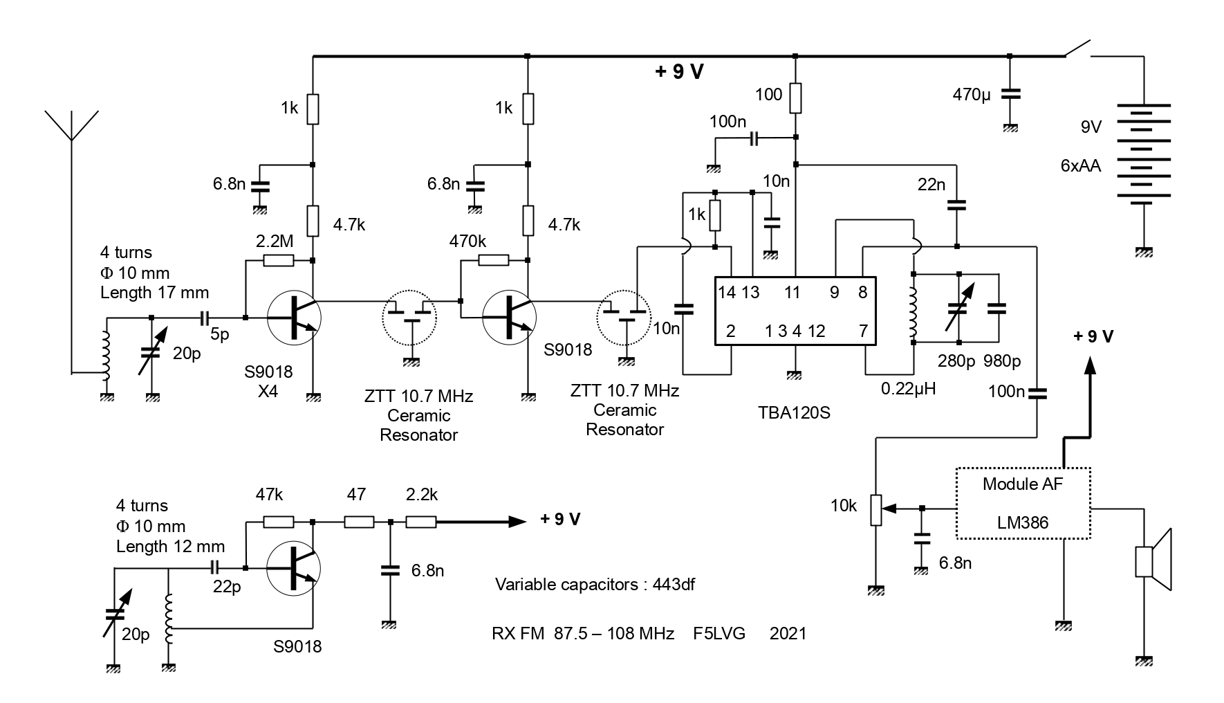
Let's study the selected schematic. The oscillator is conventional. It is tuned 10.7 MHz below the received frequency. It is coupled to the mixer stage by its simple RF radiation. The mixer stage consists of 4 transistors in parallel. Having a tower with 8 transmitters of 2 kW at 2.4 km from my home, the phenomena of inter modulation and saturation of the first stage are major. They make it difficult to receive other transmitters 40 km away. I imagined that putting several transistors in parallel would reduce these saturation phenomena. Indeed, a clear improvement has been obtained by the paralleling of 4 transistors, without however being able to determine if it is really a reduction of the saturation phenomena or the obtaining of a more favorable operating point. A first IF amplifier stage made with a transistor follows. The inter-stage connection is made with ceramic resonators which give selectivity to the receiver. The next stage is a TBA120S integrated circuit which performs a new IF amplification and then limits the signal to a constant level before demodulating it. A ready-made module, based on an LM386 IC, provides the low frequency amplification for loudspeaker listening. The power supply is 9 V, obtained by 6 AA batteries.
Let's talk about some particular points.
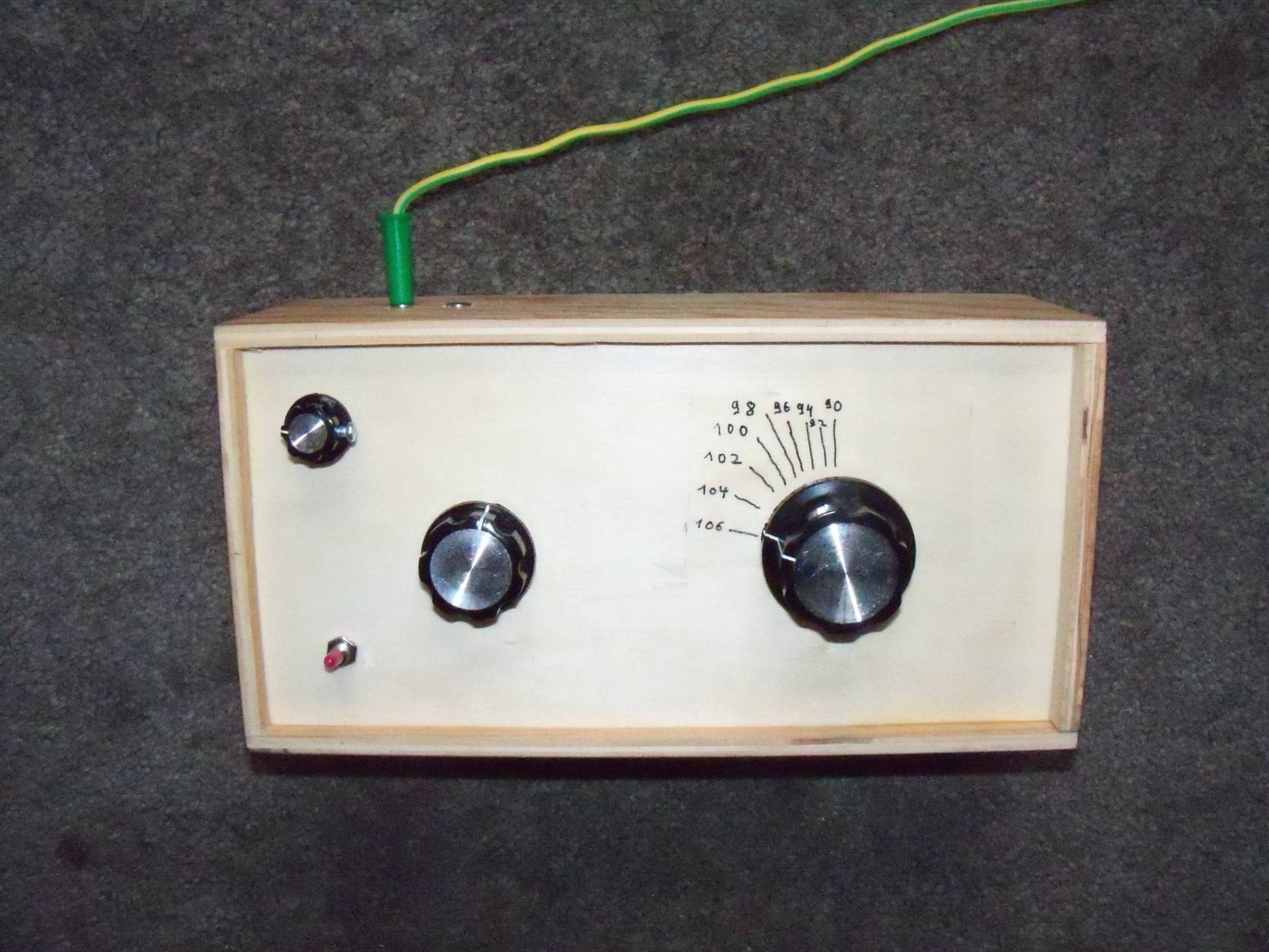
The variable capacitors are 443df. They are made of 4 sections 2 x 20 pF and 2 x 120 pF. A 20 pF section is used at the input and at the oscillator. All the sections are used at 10.7 MHz. The 3 ground strips must be soldered to ground. It is easy to attach a button by inserting a 20 mm x 2.5 mm screw on the central axis. Because of the absence of gearing, a large knob is necessary. The MF-A05 knob is perfect. A simple way to fix these variable capacitors is to glue them with cyanolite (superglue).
The tuning and oscillator coils are made of 10A wire.
The coils of the input and oscillator circuits must be connected directly to the variable capacitor and to the ground, without any intermediate connection.
For selectivity, ceramic oscillator resonators (ZTT 10.7 MHz) are used. They are less selective than ceramic filters, which facilitates the adjustment of the stations in the absence of variable capacitor gearing. However, it is possible to clearly separate stations spaced at 300 kHz. If you use ceramic filters, you risk self-oscillations, their insertion losses being lower. In this case, a very small capacitor (5 - 10 pF) should be placed between the collector of the IF transistor and ground.
The resonant circuit connected to the TBA120S gives the necessary phase shift to obtain a correct coincidence demodulation. It is essential to use a low L/C ratio. Initially, it is simpler to use a 2.2 µH coil and the variable capacitor without any fixed capacitor. The approximate setting corresponds to the minimum background noise in the absence of a station. After having obtained the operation of the receiver, it is necessary to change the coil (0.22 µH), to add fixed capacitors (680 pF + 120 pF + 180 pF) and to seek the best point of demodulation on a weakly received station.
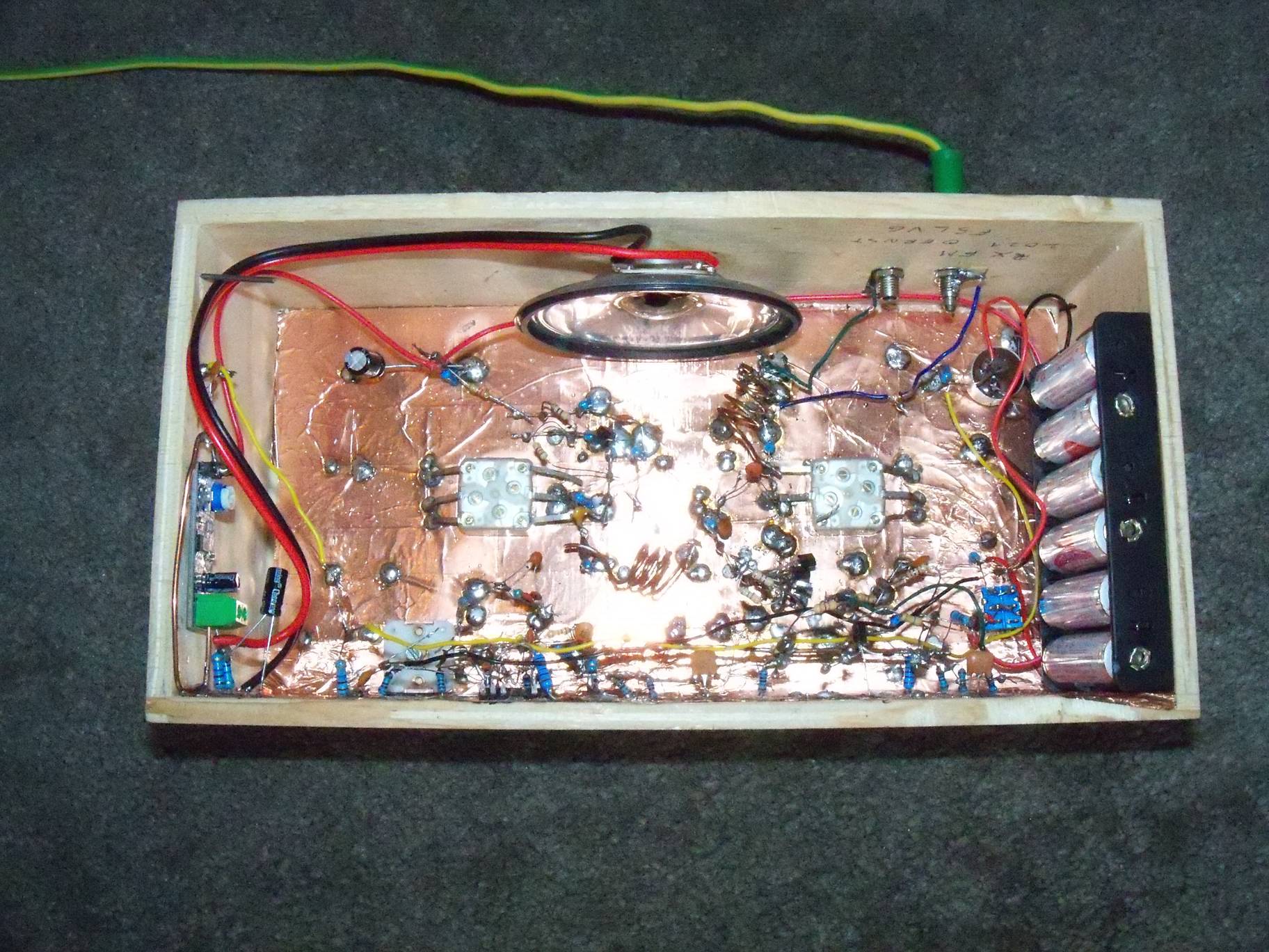
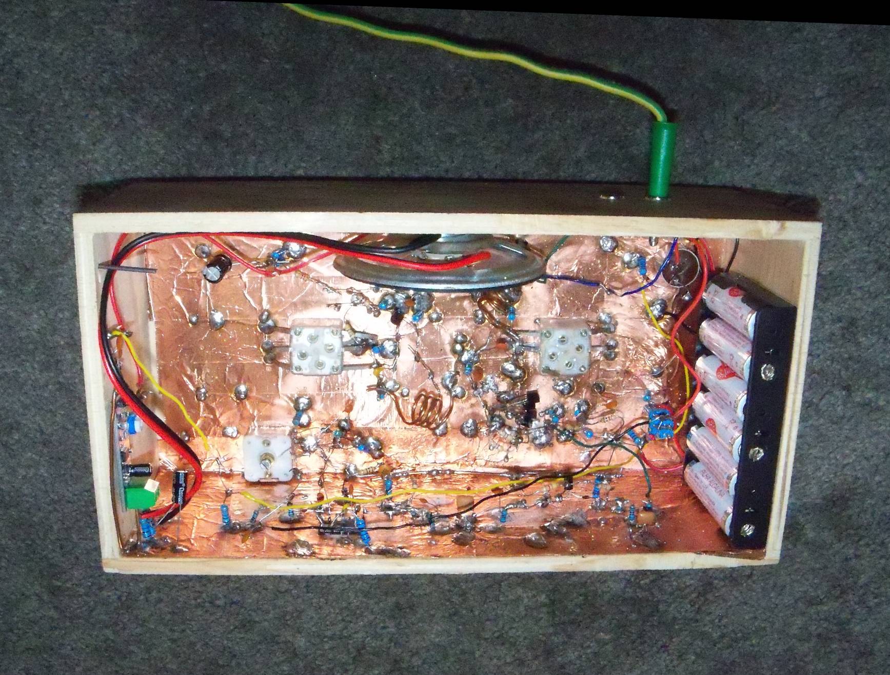
The assembly is made in a wooden box designed for tissues. The front face with a slot is removed. The inside (except the upper face) is covered with self-adhesive copper strips of 50 mm overlapping a few mm to make the ground plane. Some soldering points are made between each strip to perfect the electrical contacts. Resistors of 10 Mohms are used to make connection points when necessary. Their resistance is negligible. The loudspeaker is glued with cyanolite on the top side.
The highest frequency of the oscillator must be 97.3 MHz to receive the highest frequency of the FM band (108 MHz). The value of the variable capacitor being at the minimum, it will be necessary to adjust the coil and the trimmer integrated in the variable capacitor so that the oscillation is 97.3 MHz. Indeed, if the frequency is higher, we will receive from 98.2 MHz the low part of the band (87.5 MHz). When the variable capacitor is at maximum, the frequency of the oscillation is well below 76.8 MHz. The FM band occupies approximately 2/3 of the rotation of the oscillator knob. We can improve the spread by putting in series with the variable capacitor a fixed capacitor of 33 pF.
When disconnecting the second ceramic resonator of the TBA120S, one should hear some hiss in the loudspeaker. When reconnecting the resonator to the TBA120S, the hiss should increase significantly. If it disappears, this is evidence of self-oscillation of the IF transistor.
The antenna is a 40 cm long 20A wire ending with a banana plug. A real telescopic antenna would be perfect.
For strongly received stations, the adjustment of the variable input capacitor is almost unnecessary. For weakly received stations, this adjustment is essential. The best setting corresponds to the minimum hiss in the receiver. Because of the very weak coupling between the oscillator and the mixer, there is no pulling between the two settings.
F5LVG 2021