A simple, high-performance superheterodyne receiver for amateur band reception (SSB-CW) from 3.5 to 30 MHz can easily be built using the following rules:
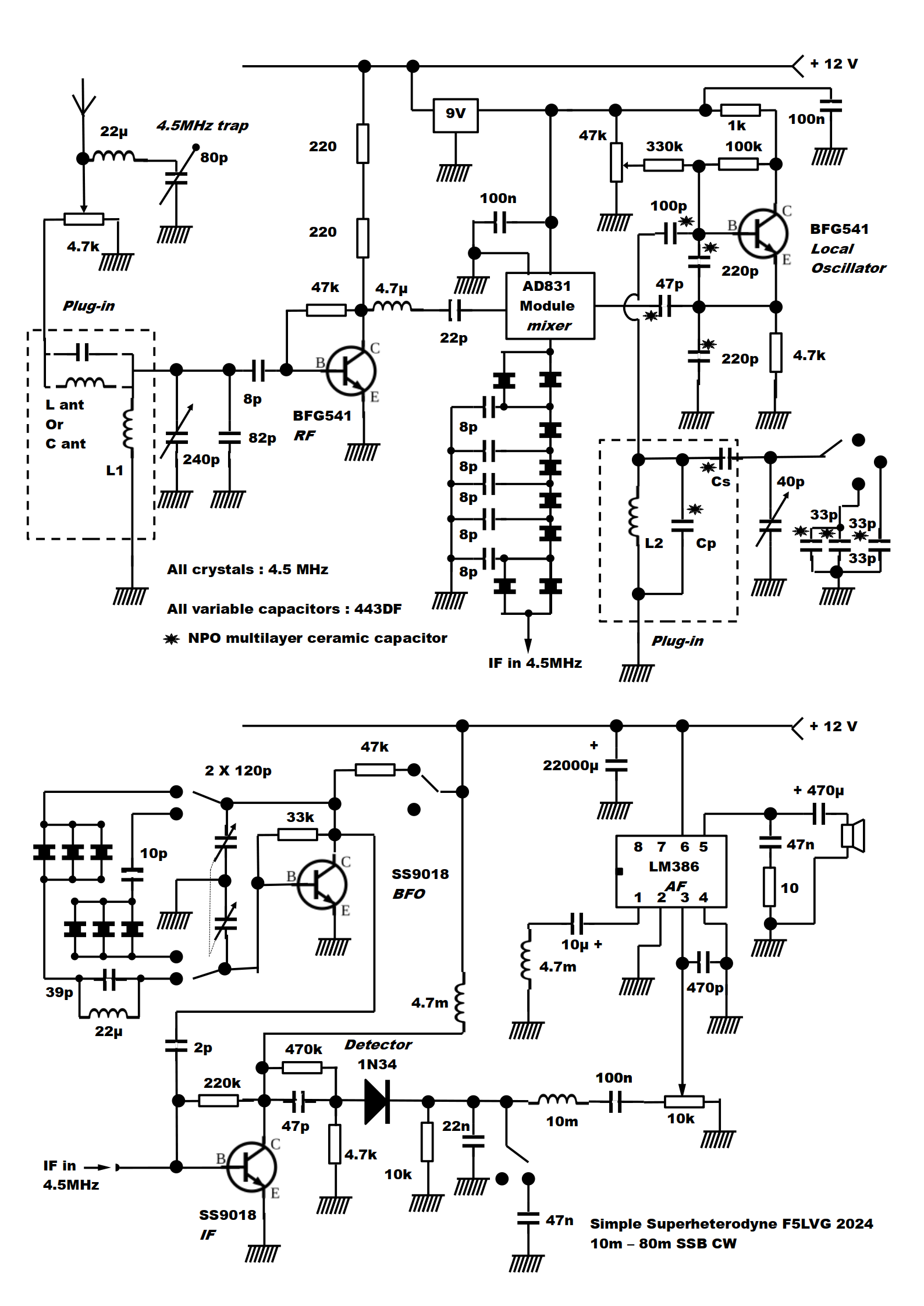
1 Use modern bipolar transistors (BJT) because they are efficient, robust and cheap. Two exceptions: the audio output stage because AF integrated circuits require far fewer components than BJT circuits, and the mixer stage because BJT have very poor resistance to crossmodulation and saturation. A module with an AD831 is used in the mixer stage. Its resistance to crossmodulation is similar to that of a balanced diode mixer, while requiring very little power from the local oscillator.
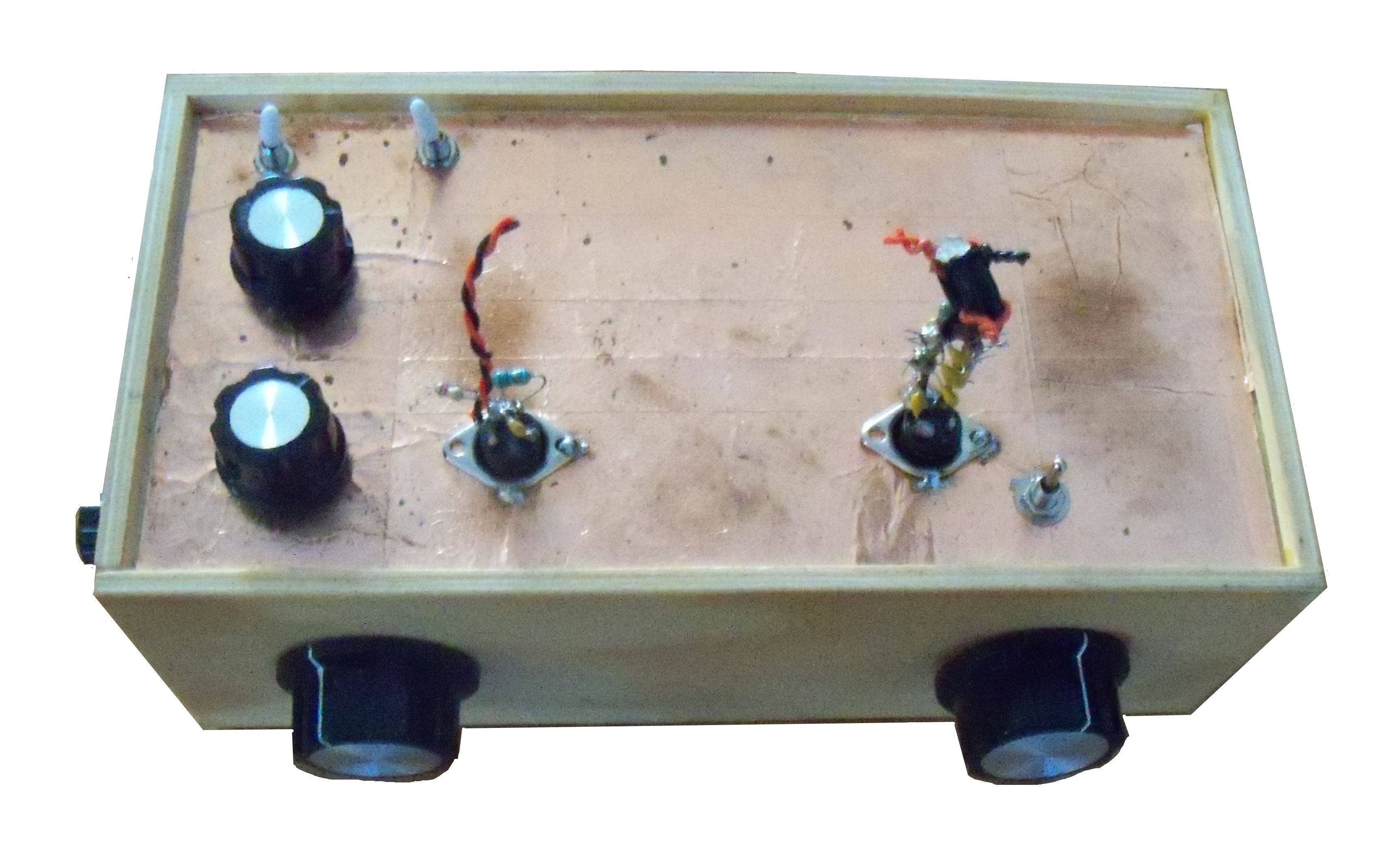
2 Use of small AM-FM plastic variable capacitors (443DF), without any reduction drive system. Each frequency band is divided into 3 and a large tuning knob is required (A05). The variation in the voltage applied to the base of the oscillator transistor is used for fine tuning.
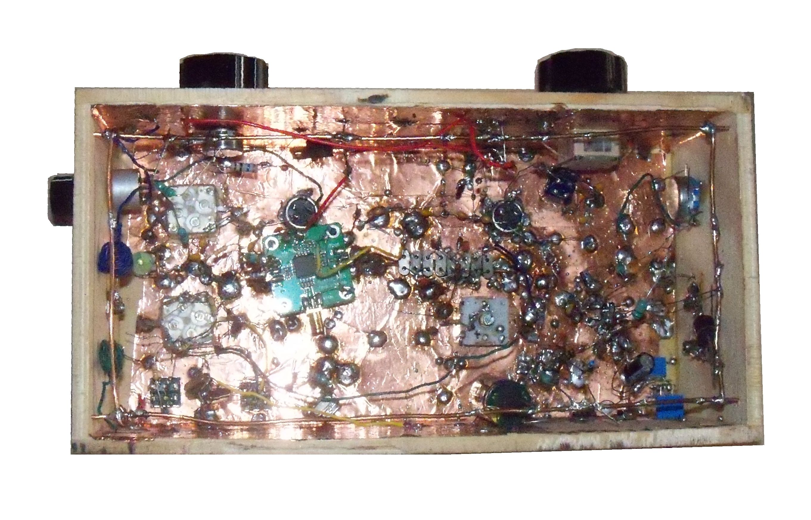
3 Choice of plug-in resonant circuits for easy assembly and excellent performance.
4 Use of a tuned input resonant circuit with high capacitance to improve selectivity and attenuation of the image frequency.
5 Use of NPO multilayer ceramic capacitors in the oscillator stage.
6 Choice of Seiler for the local oscillator with a high C/L ratio (high C) to obtain good frequency stability.
7 Use of a high intermediate frequency (4.5MHz) to strongly attenuate image frequencies.
8 Use of a 6-pole QER quartz filter for selectivity.
9 Use of a single active element per stage to avoid harmful auto-oscillations. For the IF amplifier, no regeneration can be tolerated at the risk of distorting the bandwidth of the quartz filter and obtaining an unbearable ringing effect.
10
Short rf connections.
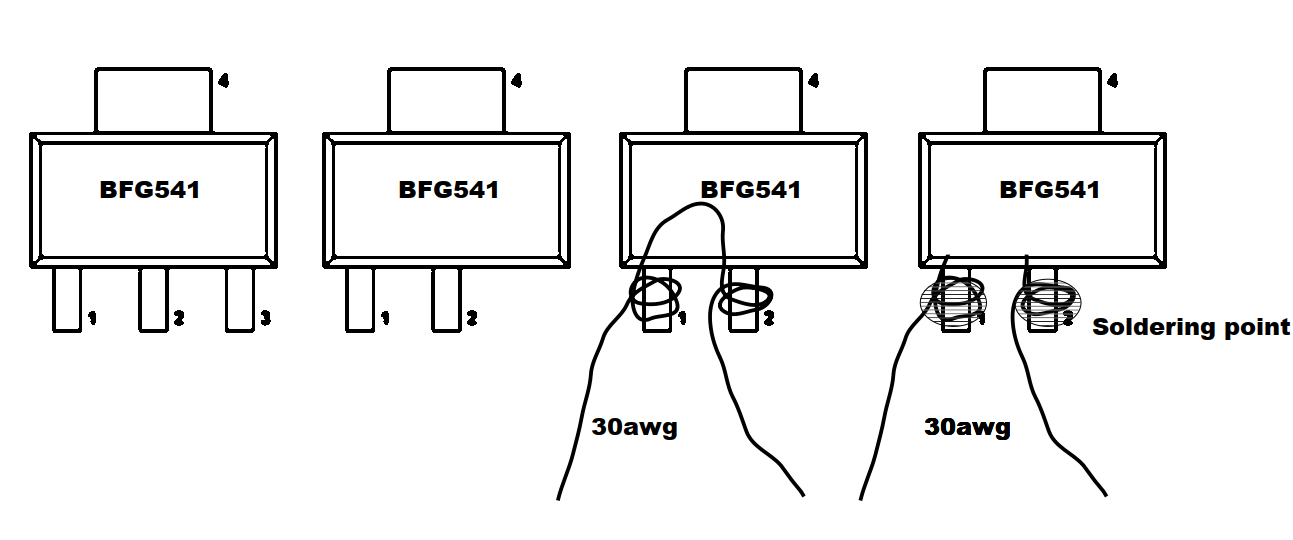
The receiver uses 2 SMS BFG541 transistors. These large SMS transistors are easy to use. First, cut pin 3, which corresponds to a second emitter output. Then wrap a 30AWG stripped wire around pins 1 and 2 (emitter and base). Apply a soldering point to pins 1 and 2 and finish by cutting the wire between these 2 pins. The collector (pin 4) is large, so it's easy to solder a resistor or capacitor to it.
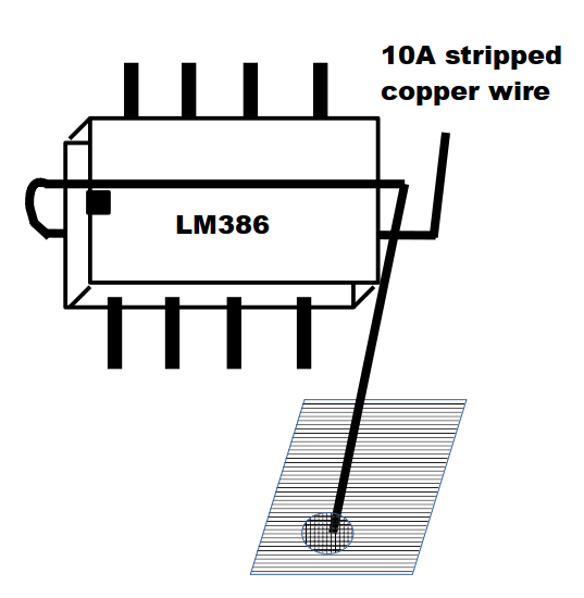
It is sometimes difficult to use integrated circuits in DIP boxes, as is the case with the LM386. Here's a simple method. First, I recommend horizontalizing the pins of the IC, which makes them easier to solder. Then use a 10 A mains wire stripped of about twenty centimetres. Bend this wire into a tight V and place the IC in the centre of the V. Then bend the 2 ends of the wire, the lower part upwards and the upper part downwards. The integrated circuit is trapped in a frame formed by the copper wire. Finally, cut the 2 ends of the wire approximately 2 cm from the integrated circuit. The integrated circuit is fixed by soldering the end of a wire to the ground plane.
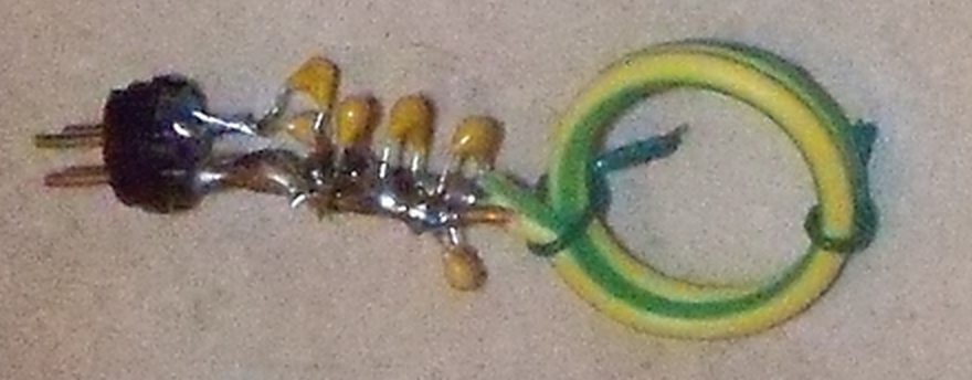
The AD831-based mixer module can be fixed in the same way by wrapping 2 stripped wires around the 2 RFin and IFout connectors. The 2 wires are then soldered to the connectors, and one end of each wire is used to attach the module to the ground plane.
The input resonant circuit is coupled to the antenna by a capacitor if the oscillator frequency is lower than the received frequency (10m-17m), and by an inductor if the oscillator frequency is higher (20m-80m). This coupling improves image frequency rejection.
The oscillator coils are made from 10A (1.5 mm2) mains wire. They are attached directly to the DIN plug pins. The coils are glued with cyanolite glue when everything is ready. To increase frequency stability, the capacitor Cp is an assembly of several NP0 capacitors, with each capacitor limited to 220 pF. The higher the value of Cp, the more stable the oscillator frequency. The value of Cs is determined to cover only the desired frequency range.
This receiver isn't perfect. There is no automatic gain control, the bandwidth is not adjustable, there is no S meter and the frequency display is inaccurate. On the other hand, the noise figure is good, reception is single-signal and frequency stability is good, even over 10 m. On a 2 x 10 m antenna, I've received JA, CE, VE and many other countries from the north of France.
40 m Lant 10µH, L1 2.2µH, L2 2 turns ϕ 22mm, Cp 1222pF, Cs 100pF
20 m Lant 4.7µH, L1 1µH, L2 2 turns ϕ 10mm, Cp 980pF, Cs 100pF
17 m Cant 8pF, L1 0.47µH and 1µH in parallel, L2 2 turns ϕ 14mm, Cp 1380pF, Cs 69pF
15 m Cant 8pF, L1 0.47µH and 1µH in parallel, L2 2 turns ϕ 14mm, Cp 850pF, Cs 100pF
12 m Cant 8pF, L1 0.22µH and 1µH in parallel, L2 2 turns ϕ 10mm, Cp 893pF, Cs 27pF
10 m Cant 8pF, L1 0.22µH and 1µH in parallel, L2 2 turns ϕ 10mm, Cp 682pF, Cs 100pF
Olivier
ERNST F5LVG 2024