"Regenerative Receivers: Tubes or Transistors? The Choice is Yours!
The principle of regenerative receivers was discovered in 1912 by Edwin Armstrong, followed by a patent in October 1914. It was a simple method to achieve extremely high gain from a vacuum tube with low inherent gain. In 1933, experimental measurements showed that a gain of 5000 could be achieved by applying regenerative techniques to a tube with a gain of 9 without feedback (Robinson HA, QST, February 1933, p27). Until the early 1930s, almost all receivers utilized this regenerative technique to enhance the weak amplification obtained from tubes of that era. Besides the significant gain, regenerative receivers can demodulate amplitude modulation (AM) signals, as well as single-sideband (SSB) signals. Even today, it is possible to hear relatively simple receivers picking up radio amateurs from New Caledonia or Australia on 20m in SSB. I have personally conducted several two-way communications with North America using the two regenerative receivers described in this article, a homemade transmitter (100W), and a 2x10m Levy antenna on 21MHz and 18MHz.
Principle of regeneration
The principle of regenerative involves reapplying a portion of the output signal from an amplifier back to its input. This signal, reintroduced at the input, is then amplified, significantly increasing the stage's gain. In theory, this can lead to infinite gain, and the amplifier begins to oscillate – this is called "feedback." In practice, the feedback circuit is adjusted just before the onset of oscillation for AM stations and just after for SSB or Morse code (CW) stations. The frequency emitted by the feedback circuit reconstitutes the missing carrier for SSB stations, allowing interference-based CW decoding. In most cases, the feedback occurs at the detector stage (demodulator).
Effect of Feedback
Feedback greatly increases the gain of an amplifier stage. If a selective circuit is placed in the feedback loop, amplification gain is primarily achieved at the tuning frequency of this circuit. Selectivity is thus significantly enhanced near the point of feedback. In practice, the selective circuit can be a simple resonant circuit consisting of an inductor and a capacitor (LC circuit).
Antenna Coupling
The antenna can be directly coupled to the receiver's resonant circuit. However, this results in several issues that degrade the performance of these receivers. First, significant damping is introduced to the resonant circuit. This leads to a decrease in sensitivity and selectivity. The second issue is the degradation of frequency stability. Due to wind influence, the antenna moves, causing variation in capacitance between the antenna and ground, which in turn alters the tuning of the resonant circuit. The third issue is the risk of audible interference, especially above 10 MHz. Therefore, an amplifier stage must be placed between the antenna and the resonant circuit. This amplifier stage should have a wide bandwidth for ease of assembly. It should operate below saturation and be as linear as possible, especially given that bipolar transistors have limited linearity. Feedback is essential for good results. A potentiometer at the input of the amplifier stage is necessary to reduce saturation. This non-tuned amplifier stage must also have low noise and high-frequency (HF) amplification (3 MHz to 30 MHz).
Frequency Stability
Receiving SSB requires frequency stability better than 100 Hertz. When comparing this to the 14,000,000 Hertz on the 20m band, it's clear that achieving such frequency stability is challenging. To achieve this, a number of criteria must be met:
Robust mechanical construction.
A front panel made of copper or aluminum, connected to ground to avoid the hand effect.
A regulated power supply for the entire receiver.
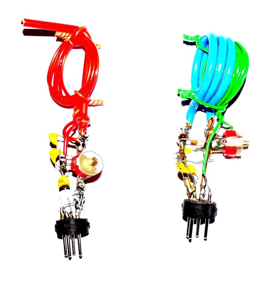
No tuning of the resonant circuit. In practice, this is not feasible. It would require a variable capacitor for each frequency band. Instead, a single variable capacitor is placed in series with a low-value capacitor, selected to cover just the desired frequency band. The resonant circuit is constructed on a DIN plug and includes the coils and fixed capacitors.
High-quality components to minimize losses and time-dependent variations. The coils are constructed with thick wire, and the fixed capacitors must be of the NPO type. Adjustable capacitors should be of good quality. Cheap Chinese models should be avoided.
Use of high-value fixed tuning capacitors (low L/C ratio). As a reference, a tuning capacitor of over 500 pF should be used to achieve good stability in my experience, which is achievable up to 21 MHz. Note that for a tube-based setup, the higher the tube's transconductance, the more significant capacitors can be employed.
Background Noise
Regenerative receivers, like all receivers, face the usual sources of noise. However, there are two specific noise sources for regenerative receivers and direct conversion receivers.
Feedback hum on the high-frequency bands (< 10 MHz). This hum is called "tunable hum" by the Anglo-Saxons. Its explanation is simple. When in feedback, the resonant circuit emits a wave whose frequency corresponds to the received frequency. This wave is modulated at 50 Hertz by one of the multiple nearby AC power supplies. The cable from these power supplies acts as an antenna. The 50 Hertz modulated wave returns to the regenerative receivers, superimposing a strong 50 Hertz modulation on the station being received. A head stage is essential to minimize this source of hum. The diodes of the power supplies near the receiver should all be connected in parallel with a capacitor of approximately 10 nF. Ideally, the entire receiver should be shielded. If not, above 10 MHz, smaller diameter coils should be used, as they will radiate less than larger diameter coils.
Induction of mains noise on the grid or base of the regenerative detector. The grid of the regenerative detector tube or the base of the regenerative detector transistor presents high impedance to 50 Hertz currents. The small capacitance between the wires carrying 50 Hertz and the grid or base connection is sufficient to introduce a relatively significant 50 Hertz voltage. This grid or base connection should be as short as possible. Additionally, the impedance for the 50 Hertz current should be minimized. For a tube, the grid resistance should be as low as possible while still allowing sufficient amplification. For a transistor, the base should be connected to the resonant circuit through a capacitor with low impedance for 50 Hertz currents. In practice, its value should be close to 0.1 µF (100 nF).
Selected Designs
I wanted to create two designs, one with tubes, the other with transistors. The tube-based design aimed to resemble older designs as closely as possible, so I chose to use octal tubes. The block diagram of the receiver is identical for both techniques: non-tuned amplifier, regenerative detector stage, two audio-frequency amplifier stages.
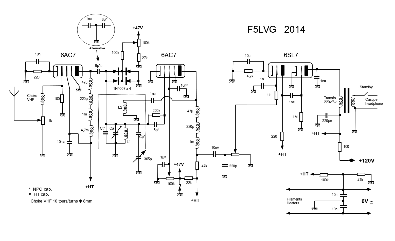
Characteristics of the Tube-Based Receiver
The 6AC7 tube was chosen as the RF amplifier and detector because it has the highest transconductance among octal tubes. This tube has also been manufactured in Russia under the designation 6j4 (6Ж4), which is significantly cheaper than the American production while offering similar quality. The 6SL7 tube was chosen as the AF amplifier, with a higher amplification factor, well superior to that of the 6SN7. Again, there is a good quality Russian version, the 6N9S (6N9C). The filament wiring is done with two wires, with one wire connected to a positive voltage close to 40 V. This significantly reduces the 50 Hertz background noise of the detector. In the conventional single-wire connection, during the negative half-cycle, some electrons leave the filament to reach the grid connection, which is positive at that moment. The value of 220 kohms for the grid resistor of the detector is relatively low compared to the standard schematic to reduce the power line hum. The low value of the grid capacitor (8 pF) prevents the tube from oscillating at low frequencies during feedback. The variable capacitor of 365 pF is geared (three turns). This is insufficient for easy tuning in SSB. Fine tuning is therefore achieved using 1N4007 diodes that serve as varicaps. The VHF choke coil in the grid circuit of the first 6AC7 prevents self-oscillation of this tube. The 100-ohm resistor should be adapted depending on the antenna. This value works well for a transmitting antenna with a 50-ohm impedance. Listening is done exclusively with headphones. The high voltage must be regulated to 120 V.
Characteristics of the Transistor-Based Receiver
The 1N4148 diodes are used only to protect the receiver when used next to a transmitter. If this is not the case, they should be removed as they slightly increase transmodulation. Note the feedback on the RF transistor with the 10 kohm resistor and the 10 nF capacitor. The two 100 pF capacitors that are part of the resonant circuit, but are not on the DIN plug, should be wired very short. The connection between the 22 kohm resistor and the BC547C transistor should be extremely short (less than 2 cm) to avoid power line hum. Just like the tube-based design, a vernier adjustment using "varicaps" is provided.
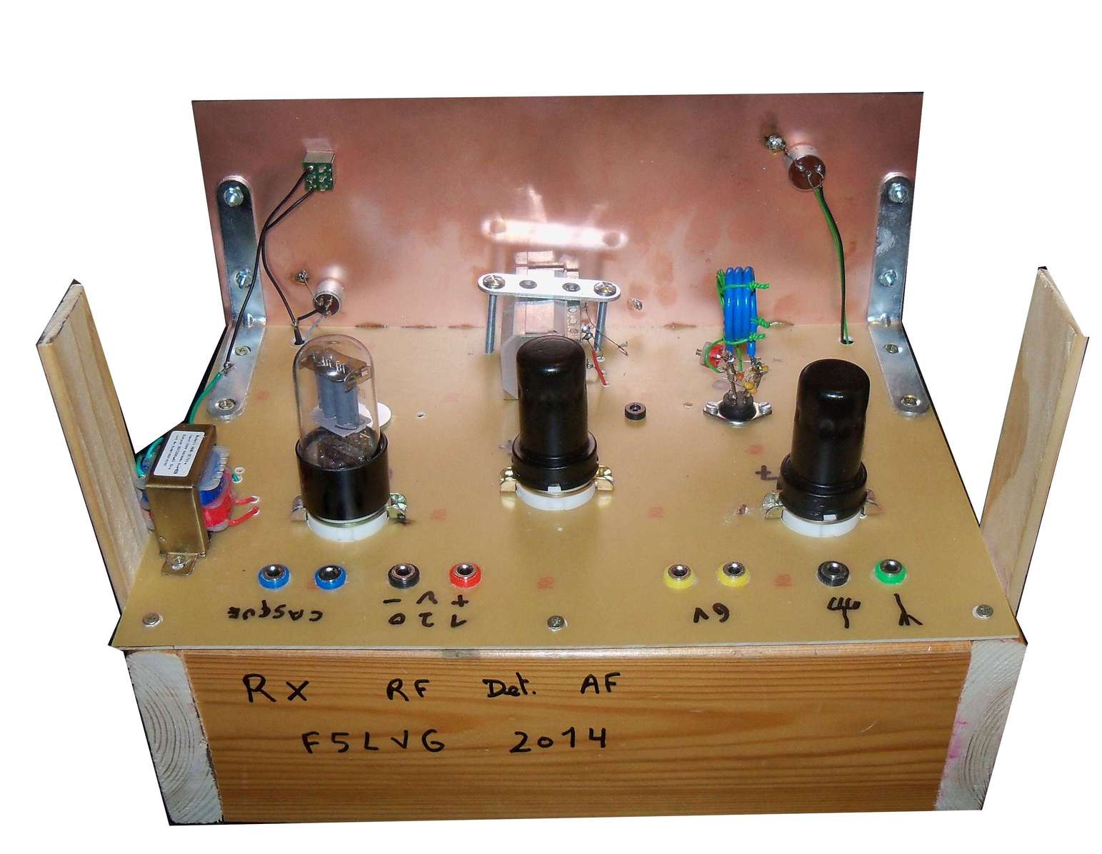
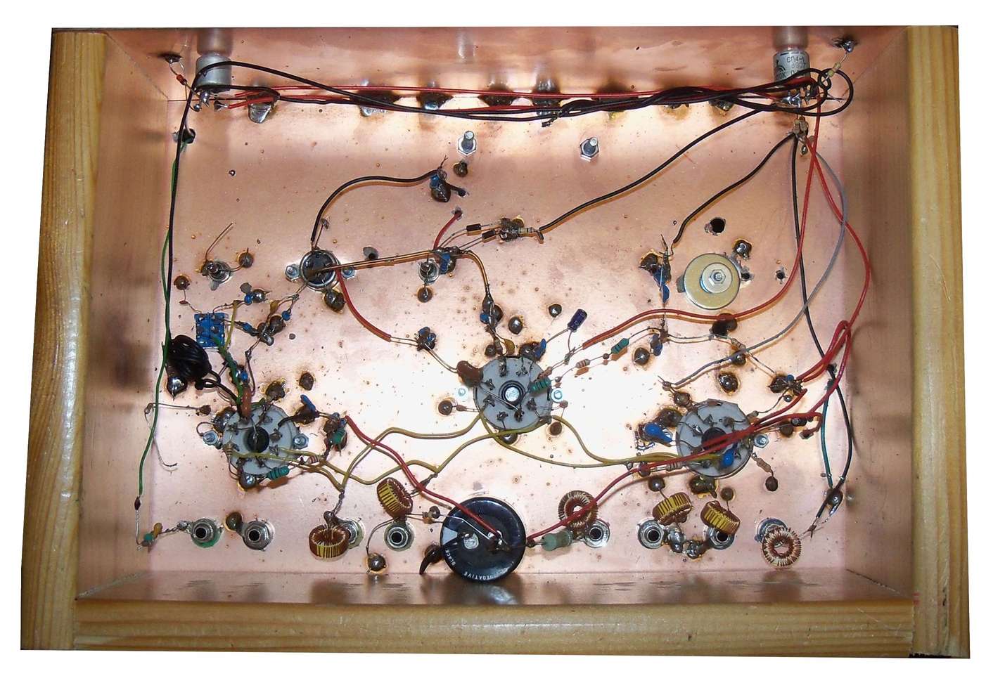
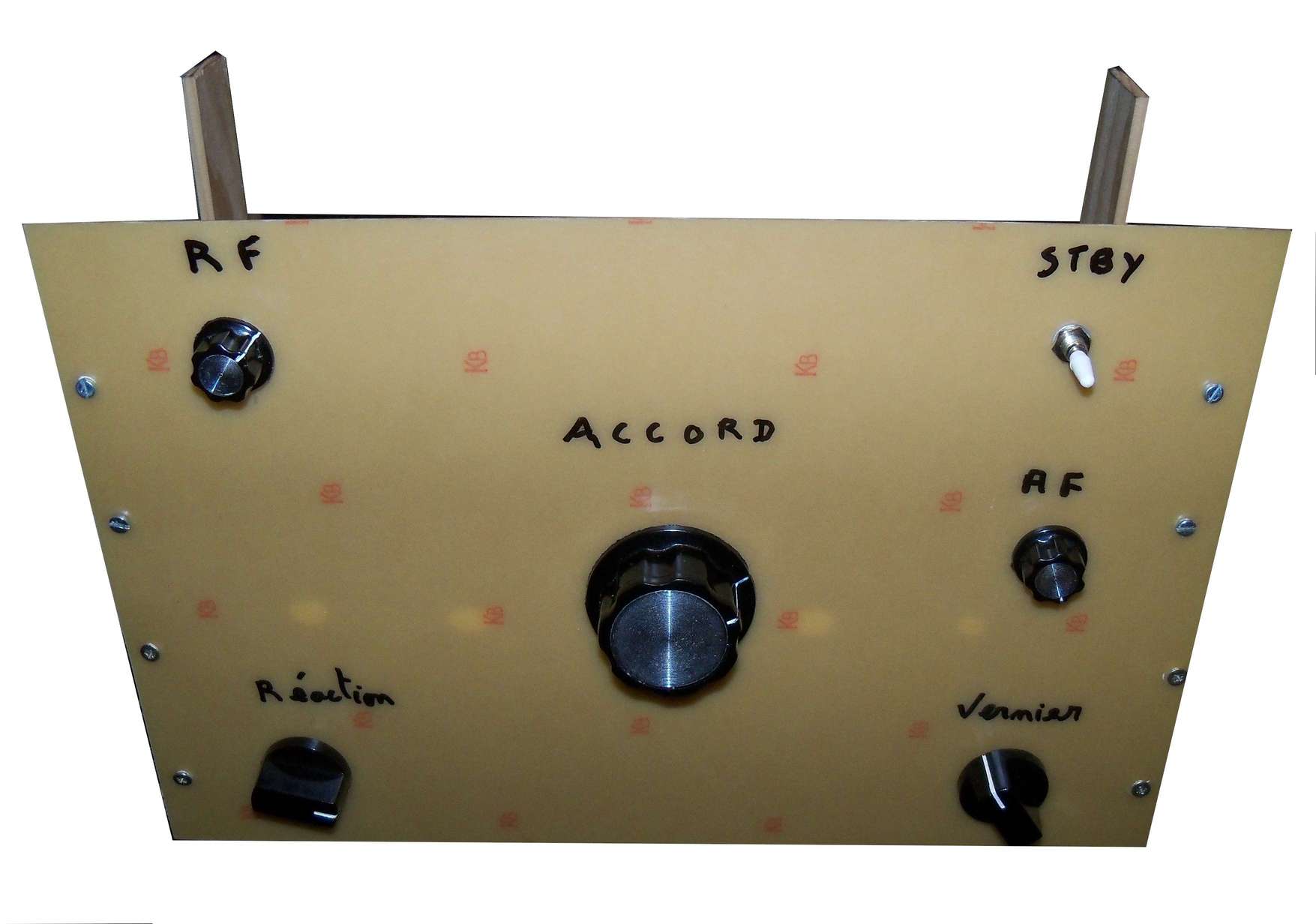
Practical Implementation
Both receivers are built on copper-clad bakelite boards. One of these boards is horizontal, the other vertical to serve as a front panel. For the tube-based receiver, the boards measure 20/30 centimeters. For the transistor-based receiver, the boards measure 15/20 centimeters. The horizontal board is attached to a wooden U-shaped base, and the vertical board is attached to the wooden support and 2 brackets. The photographs show the practical assembly. For the tube-based receiver, no source of high voltage should be accessible above the receiver to avoid the risk of electric shock. To make connection points, use 10 Mohm 1/2W resistors, twisted in pairs if necessary. Connections to the antenna, headphones, and power supplies are made using 4 mm banana plugs.
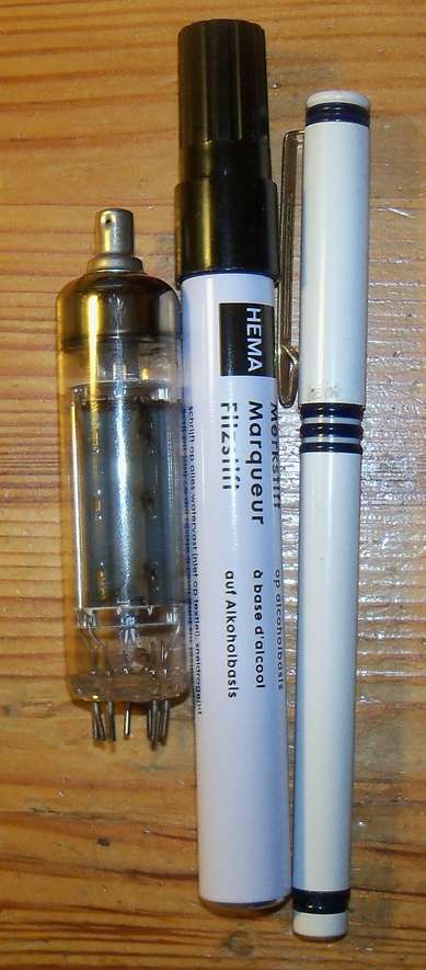
The use of interchangeable coils made with 4-pin DIN plugs allows for excellent performance. It is easy to compare 2 resonant circuits for the same band, add a new band not originally planned, etc. Above 10 MHz, the coils of the resonant circuit are made with 20 A installation wire (2.5 mm²). Maintenance coils or resonant circuit coils for frequencies below 10 MHz are made with single-strand PVC-insulated wire of 0.2 mm² (conductor diameter 0.5 mm, cable diameter with PVC insulation 1 mm). To help the coils made with installation wire stay closely wound, twist a piece of fine wire around the turns at two different locations in the winding. These coils are directly soldered to the DIN plug. For resonant circuits made with thinner wire, solder a 20 A electrical wire to the DIN plug. The coil is attached with a small wire. For the tube-based receiver, the maintenance coil is directly attached to the resonant circuit coil with a twisted fine wire. The variable capacitor and fixed capacitors are directly soldered to the coil and DIN plug. 4-connection DIN plugs are sufficient. The first connection is for ground, the second for the hot point of the resonant circuit, the third for the variable capacitor, and the fourth for the maintenance coil (tube-based receiver). Templates for making the coils are a pencil with a diameter of 9 mm, a marker with a diameter of 15 mm, and a noval tube with a diameter of 22 mm. When everything is in place, glue the turns of the coils with cyanoacrylate glue.
The coils must be at least 5 cm away from the tubes due to their high temperature. The same 5 cm distance must be maintained with the front panel. Indeed, this panel slightly deforms when touched, leading to a capacitance variation if the coil is too close. For the same reason, the variable capacitor should be attached to the horizontal board. Finally, to improve rigidity, solder the 2 boards at their contact area. The variable capacitor should be geared, ideally over 3 turns (6-fold gearing, as the variable capacitor only has half a turn).
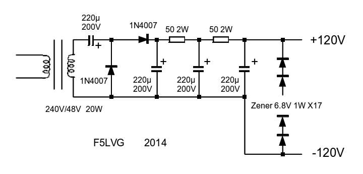
An example of a regulated 120V power supply schematic using modern components is provided.
Resonant circuits Rx Tubes
Band Diameter L1 L2 Parallel Capacitance pF Series
Capacitance pF
10m 9mm 2 7 220+82 47
15m 9mm 2 8 470+100+47 22
17m
15mm 2 6 470+22 22
20m 9mm 4 8 470+220+47 33
40m 22mm 5 5 470+47 47
80m 22mm 10 7 470+100+33 220
resonant circuits Rx Transistors
Band Diameter L Parallel Capacitance pF Series
Capacitance pF
10m 9mm 2 220+82 22+4
15m 15mm 2 330+82 22
17m 15mm 2
470+100+47 8+8
20m 22mm 2 330+220+82 33+8
40m 22mm 5 470+82 47+8
80m 22mm 11 470 100+22