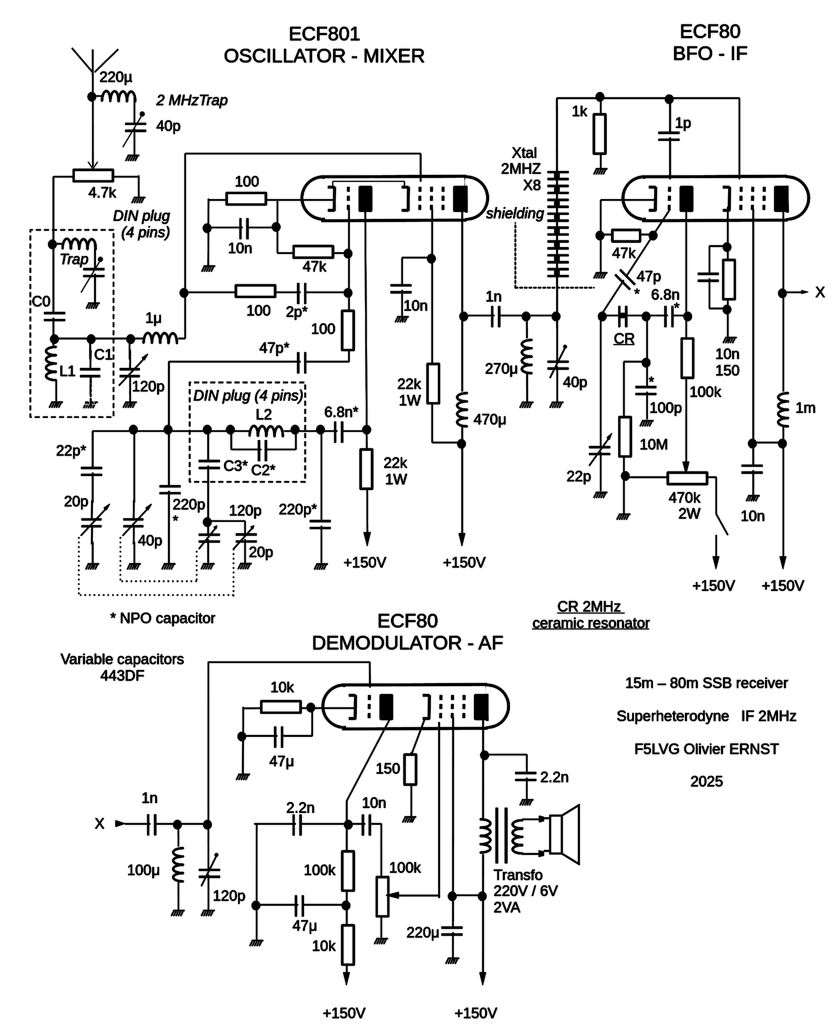
Minimalist 3 tube receiver
This receiver was designed in the same spirit as the AA5 or the wartime utility radio. The design has been optimized to achieve good performance with a minimum number of components. For radio amateurs, good performance means: SW reception (3.5MHz – 21MHz), SSB demodulation, Single Signal selectivity, sufficient frequency stability to listen to a station for 15 minutes without retuning, low noise figure, loudspeaker listening.
Here are the key design points:
1 A single stage for each function (mixer, HF oscillator, IF amplifier, BFO, demodulator, audio amplifier).
2 Use of 3 triode-pentode vacuum tubes to cover all 6 functions.
3 Choice of a 2 MHz IF to attenuate image frequencies.
4 Use of a ladder crystal filter to achieve single-signal selectivity. At 2 MHz, it is difficult to obtain sufficient bandwidth for SSB. Filter capacitances must be reduced to a minimum, i.e. to the parasitic capacitance between the crystal electrodes and the case (connected to ground). A large number (8) of crystals in series is required. The resulting bandwidth is narrow, just enough for SSB speech.
5 Use of a real (cathode to the ground) High-C Colpitts oscillator. Impedance variations between each end of the tuned circuit and ground have 4 times less effect than with a conventional oscillator. This type of oscillator requires a single coil with no intermediate tap, making it easy to build. In this stage, fixed capacitors must be of the NPO type.
6 An ECF801 was chosen for the converter tube. This is a frame-grid tube designed for band III (200 MHz). Compared to the classic ECH81, this tube offers significantly higher gain and a lower noise, which corresponds to the differences in characteristics: Sc 4.7 versus 0.77 mA/V, R noise 2.7 (calculated) versus 70 kOhm. The difficulty is to avoid VHF self-oscillations, which explains the presence of 2 x 100 Ohm resistors and a 1 µH choke in series with the control grids.
7 The BFO is a Colpitts oscillator with a ceramic resonator. It's easy to assemble and provides good frequency stability. A potentiometer is used to control the anode voltage. It allows the greatest oscillation to be used just before saturation of the IF amplifier. This ensures good SSB demodulation in the detector stage.
8 The ECF80 tube is well suited to the IF, BFO, detection and AF amplifier stages. The audio output power is sufficient for loudspeaker listening in a room with no other noise.
9 A voltage of 150V is perfectly suited to the chosen tubes. It is easily obtained from a transformer giving 110V output, followed by a bridge rectifier and a filter cell.
10 No switch for changing bands, but plug-in coils on 4-pin DIN plugs. There is no reduction gear for variable capacitors.
The
receiver is made in a wooden box with 5 cm self-adhesive copper
strips inside. Note the need for a series tuned circuit adjusted to
the image frequencies for the high bands.
On all
bands, the receiver's noise is less than that of my 2 x 10 m antenna.
The listening results are excellent (JA, VK, ZL PY, W, etc.).

Plug-in coil
15 m L1 4 turns 2.5mm² C1 47 pf C0 22pf / L2 2 turns 2.5mm² diameter 15mm, C2 522pf, C3 82pf / trap 4.7µH 30pF adjustable
17m L1 6 turns 24AWG C0 14pF / L2 2 turns 2.5mm², C2 760pf, C3 47pF / trap 4.7µH 30pF adjustable
20m L1 6 turns 24 AWG C1 22pf C0 10pF / L2 3 turns 2.5mm², C2 522pF, C3 220pF / trap 10µH 40pF adjustable
40m L1 4.7µH (miniature choke) C0 14pF / L2 4 turns 24AWG, C2 399pF, C3 68pF
80m L1 22µH (miniature choke) C0 16pF / L2 8 turns 24AWG, C2 288pF, C3 shortcut
If not mentioned: diameter = 22mm
C2 consists of several capacitors not exceeding 220pf.
The
exact values are to be adapted.
F5LVG 2025