Modern, simple, high performance 4 tubes regenerative receiver
3.5 MHz - 21.4 MHz
HAM RADIO
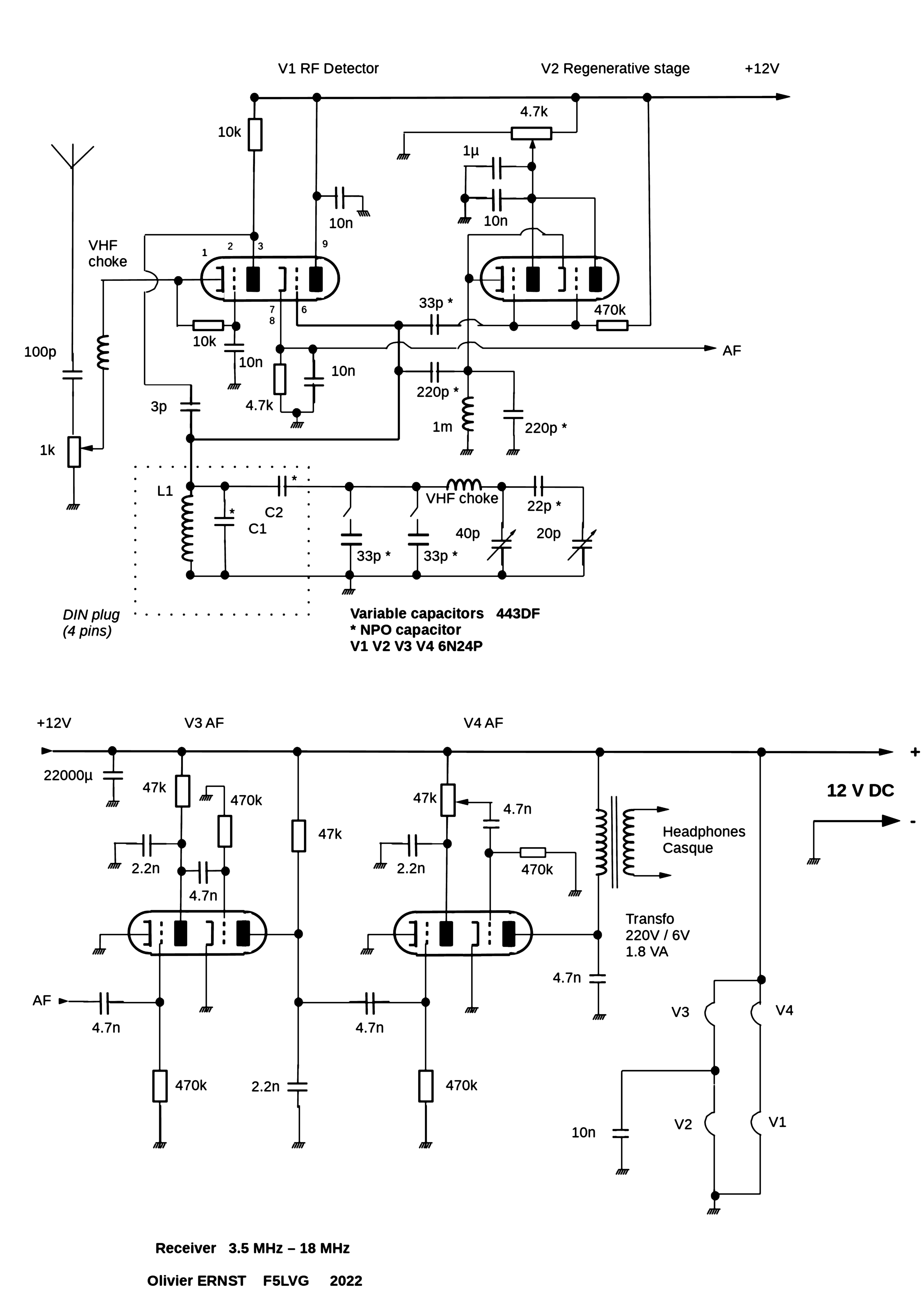
- All components are made in 2022, except the tubes (6N24P). However, if you are willing to pay 5 times the price of a nos tube, you can buy E88CC from JJ and you will have a receiver with all components still manufactured.
- A single 12V 610 ma DC power supply for the filaments and anode voltage.
Simple because:
- Only one plug-in coil per band, no intermediate tap.
- 12 v power supply.
High performance because :
- Excellent signal to noise ratio due to the absence of 50 or 60 Hz AC in the receiver.
- The use of frame-grid tubes (mandatory), "without noise".
- The use of an infinite impedance demodulator (high RF impedance, low AF impedance).
- Good selectivity. The use of tubes under 12V anode voltage requires 4 AF stages to obtain a sufficient gain. It is easy to obtain a cutoff frequency of 3 kHz for each stage. In practice, 4 KHz is enough to separate 2 SSB stations.
- Good frequency stability due to a high C resonant circuit.
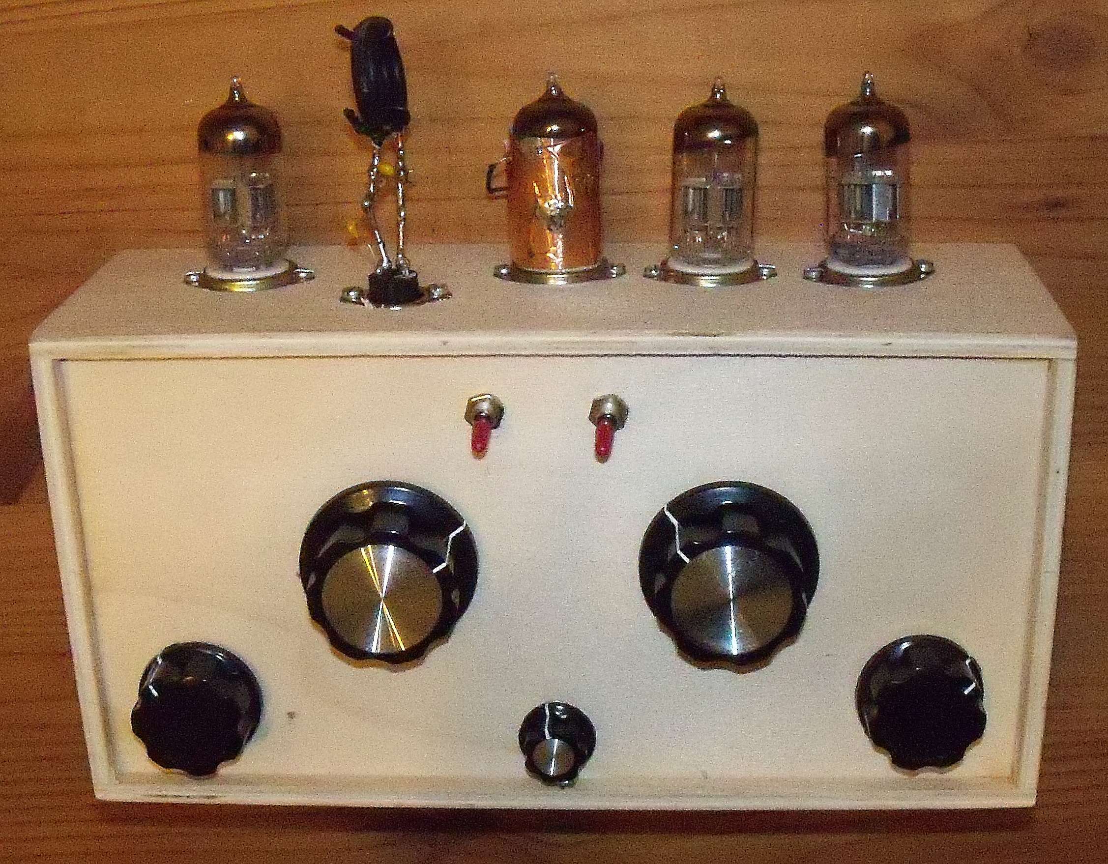
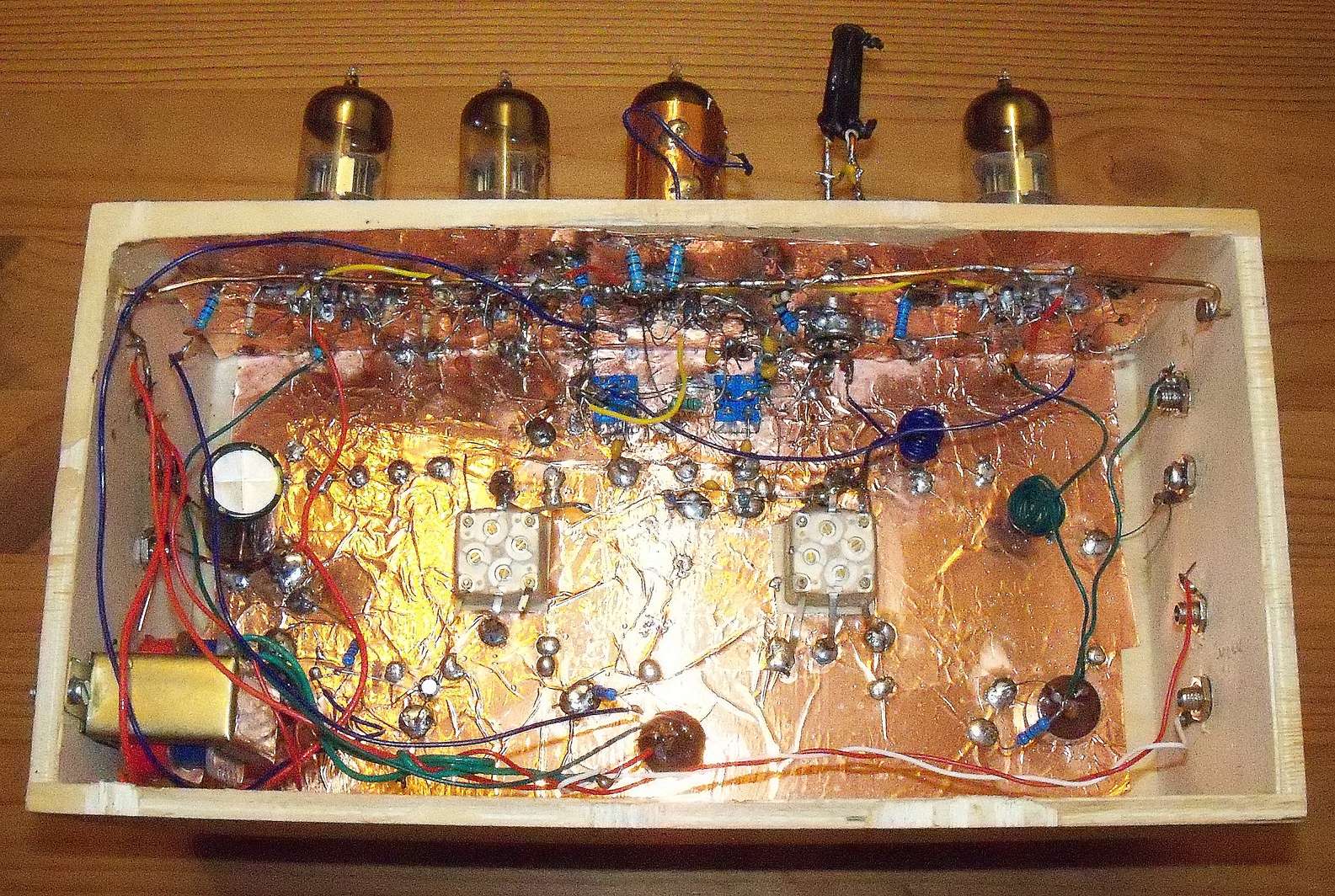
The receiver is built in a wooden box for handkerchief. Adhesive copper bands of 5 cm (for shielding) cover the inside. Resistors of 10 Mohms serve as connection points when needed.
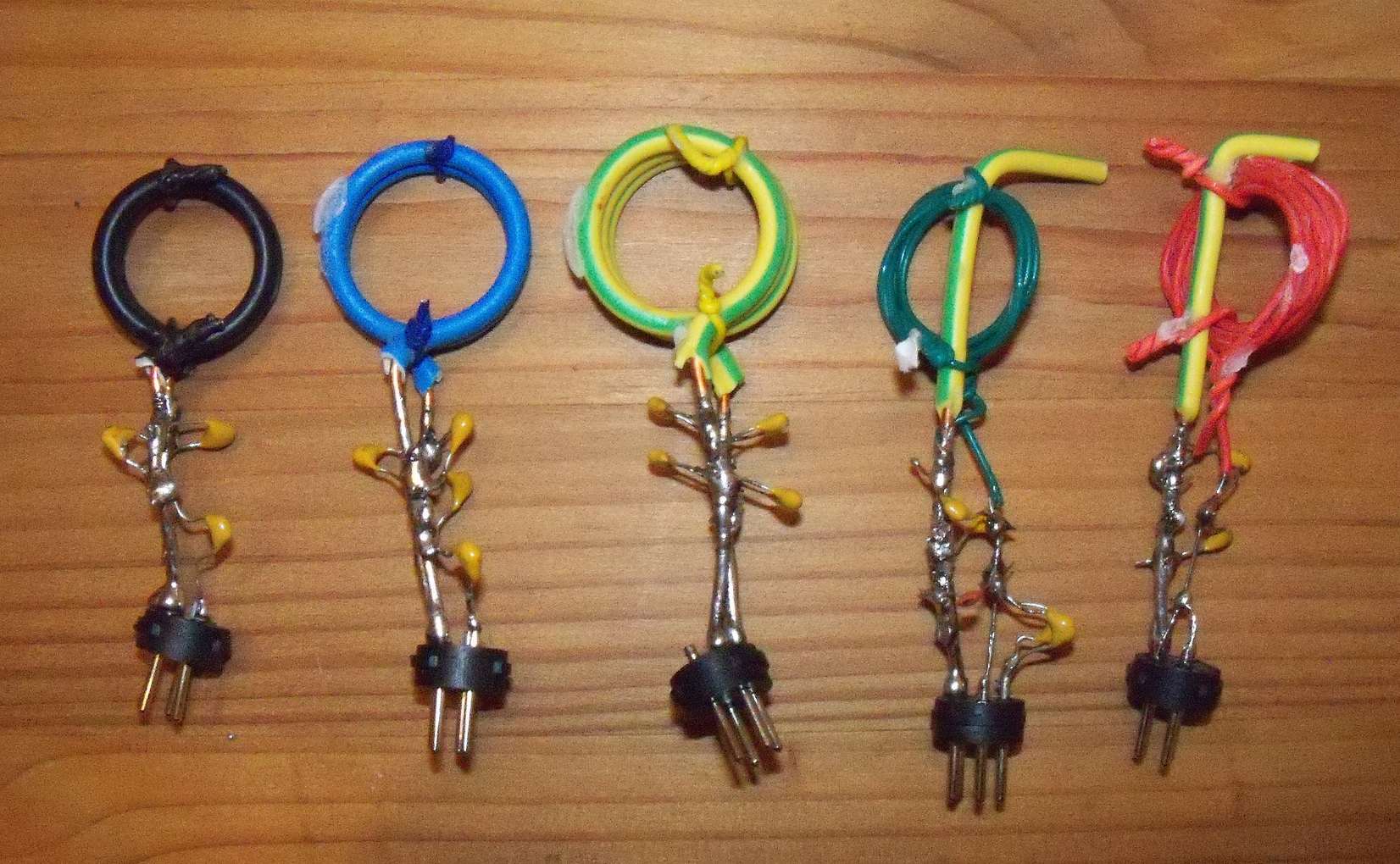
The coils are made on 4 pin DIN plugs.
For 40 m and 80 m, the coils consist of PVC insulated single wire (YV cable) with an outer diameter of the cable of 1.1 mm and 0.5 mm for the copper wire (section 0.2 mm²). These coils are fixed with 2 small twisted wires on a 20A electric wire welded to the ground pin of the DIN socket. This wire is 9 cm long, the bottom 4 cm are stripped and the top is folded back by 1 cm.
For the 15 m, 17 m, and 20 m the coils are made of 20A wire (2.5 mm² section). Two small twisted wires ensure its rigidity.
The coils are coated with cyanoacrylate glue.
The C2 value is chosen to cover only the desired band. To avoid any reduction mechanism on the variable capacitors, I split each band in 3 by 2 switches, then I use a bandset capacitor associated with a bandspread capacitor. Large knobs are needed for the variable capacitors (A05).
Notes:
- V2 is shielded to reduce the noise induced by the mains current.
- Screws of 2.5 mm diameter allow the fixation of the knobs to the axes of the variable capacitors.
- The variable capacitors are glued to the board with cyanoacrylate glue.
Build this receiver and you'll receive radio amateurs from the other side of the Atlantic! A 2022 thrill box!
Band L (turns) Diameter (mm) C1 pF C2 pF
80 9 22 470+220 Shortcut
40 5 22 330+100+12 100+33
20 3 22 220+82+8+8 47
17 2 22 330+22+5 22
15 2 19 220+47 33
F5LVG 2022