ROD TUBES 12V REGENERATIVE RECEIVER
from 150 kHz to 21 MHz
My goal was to make a tube receiver operating with a single voltage of 12V at the lowest possible current (100 mA).
I chose the Soviet tube 1j24b because the filament needs only 1.2V under 13 mA. It is a rod tube, a special series from the end of the 50's designed for particularly difficult conditions : satellites, missiles, etc. They have no grid but only rods. They are presented as cylinders of 4cm by 8.5mm from where the connection wires come out. The polarization voltage of the first rod is zero or positive.
The receiver is of the type RF amplifier, regenerative detector, AF amplifier (for headphones).
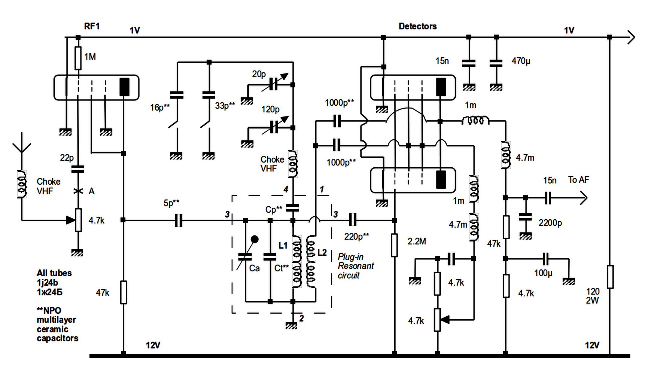
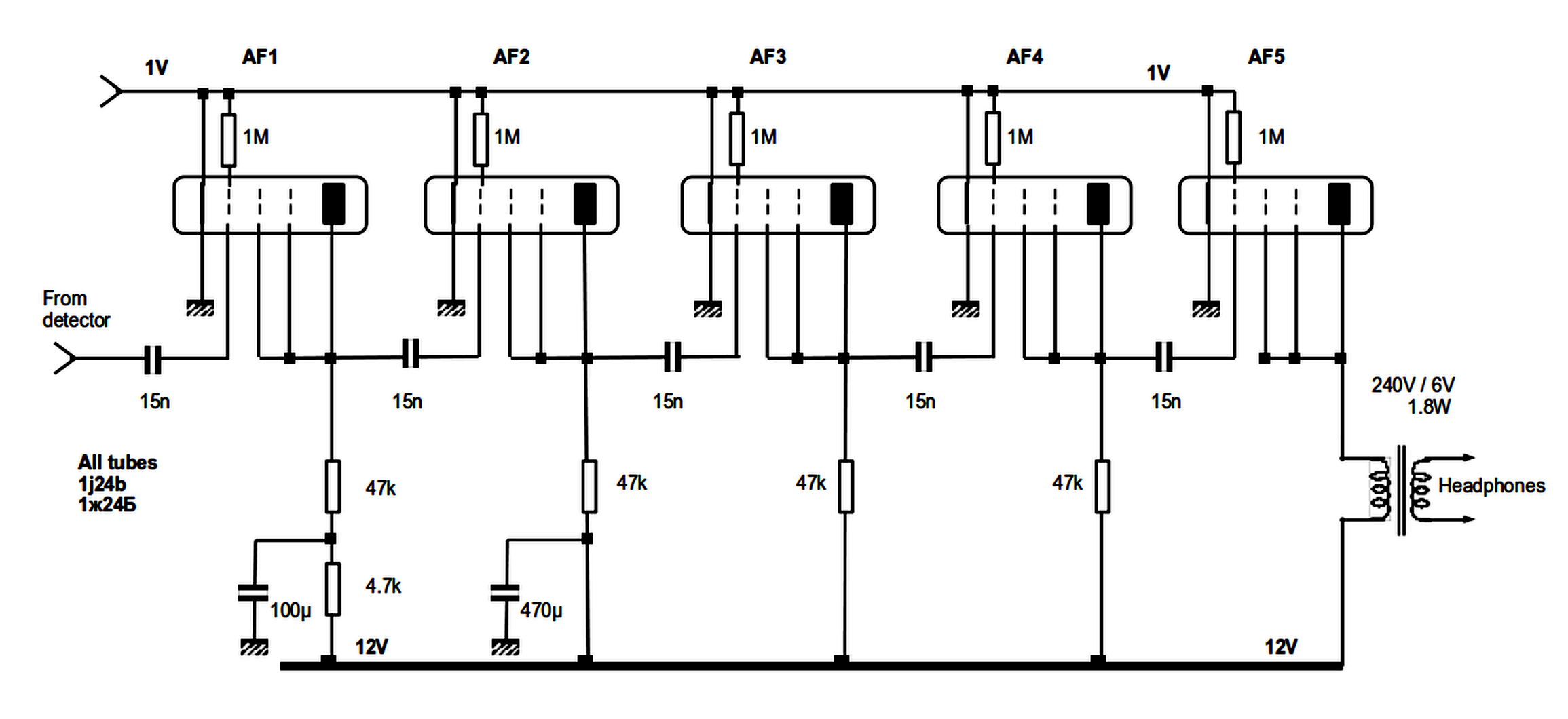
Under 12v of anodic voltage, the gain of the tubes is low. To oscillate easily above 10 MHz, 2 tubes in parallel are required to increase the slope. No less than 5 AF stages are required to obtain a high gain. In total, the receiver includes 8 tubes. By under-powering the filaments at 1.0V, the total consumption of the receiver at 12V does not exceed 100mA.
Rods 2 and 3 are connected with the L2 tickler coil in a different way from the anode in order to be able to apply the full 12V voltage to rods 2 and 3.
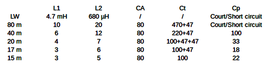
The band change is done by means of a 4 pin DIN plug. A resonant circuit is fixed on each DIN plug. The variable capacitors (DF443) of 120 pf and 20 pf are only used for band spreading. As there is no reduction gear, a large diameter knob (A05) is required. A screw M 2.5x20 mm is used to fix the knob to the capacitor axis. Cp is chosen to spread the desired band as much as possible with the 120 pF capacitor. The 20 pF capacitor is used as a vernier. The 16 pF (2 x 8 pF) and 33 pF capacitors are used to sweep a "wide range" without touching the 120 pF capacitor.
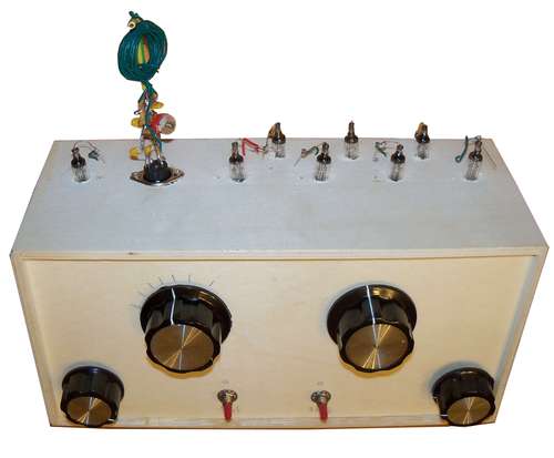
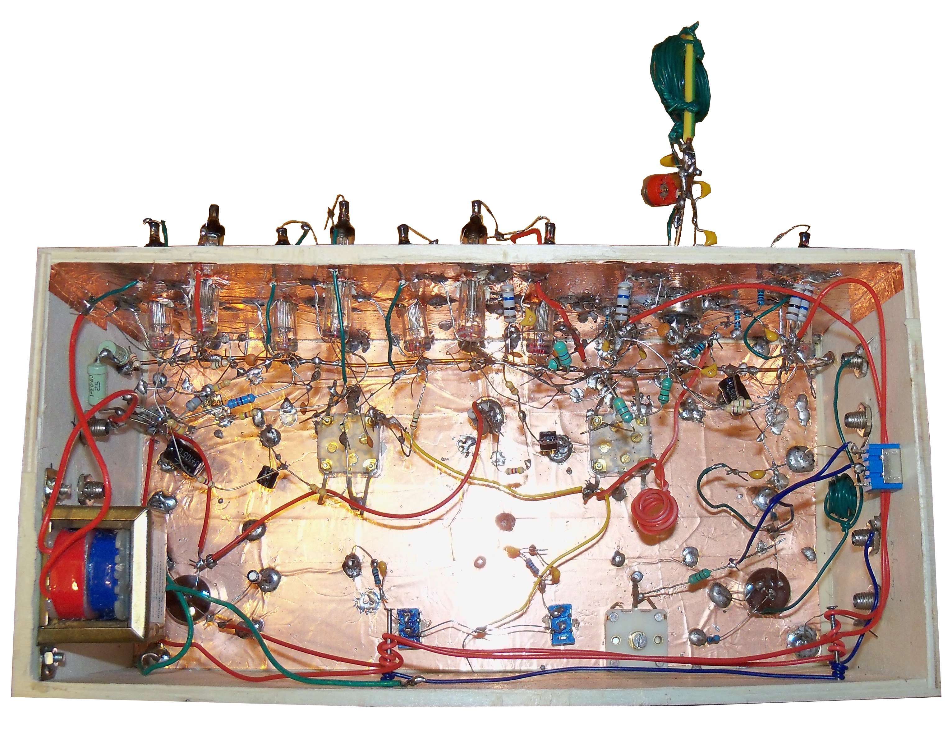
The receiver is built in a wooden tissue box with the pierced lid removed. Adhesive copper foils (5 cm wide) are used for shielding the front and top side.
Resistors of 10 Mohm serve as connection points.
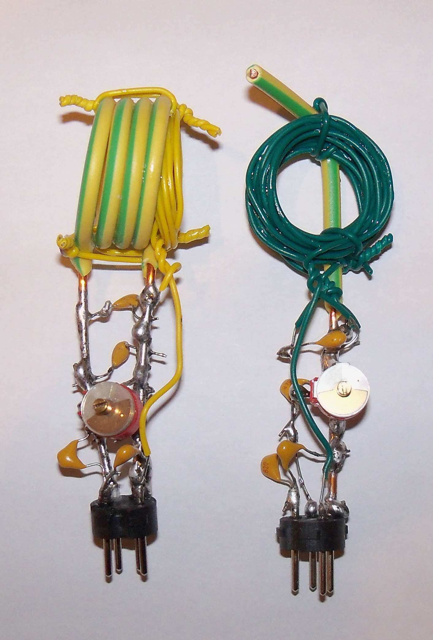
The coils for 40 m and 80 m consist of PVC insulated single wire (YV cable) with an outer diameter of the cable of 1.1 mm and 0.5 mm for the copper wire (section 0.2 mm²). These coils are fixed with small twisted wires on a 20A electric wire welded to the ground pin (2) of the DIN socket. This wire is 9 cm long, the bottom 4 cm are stripped and the top is folded back by 1 cm. One wire from the coil L1 is soldered to the stripped part of the 20A wire, the other to pin 3 having stripped the wire by 4 cm. The coil L2 is soldered to pin 1 and pin 2. The Ct capacitors are soldered between the wire going to pin 2 and the 20A wire. The Cp capacitors between the wire going to pin 3 and pin 4.
For the 15 m, 17 m, and 20 m the coils are made of 20A installation wire (2.5 mm² section) for L1 and YV cable for L2. Small twisted wires ensure the rigidity. The legs of L1 measure approximately 4 cm, are stripped and soldered to pins 2 and 3. The capacitors Ct are soldered between the leads to pins 2 and 3, the Cp capacitors between pin 3 and pin 4.
LW : miniature inductors, other bands: 22 mm diameter.
Olivier ERNST
F5LVG
01-2020