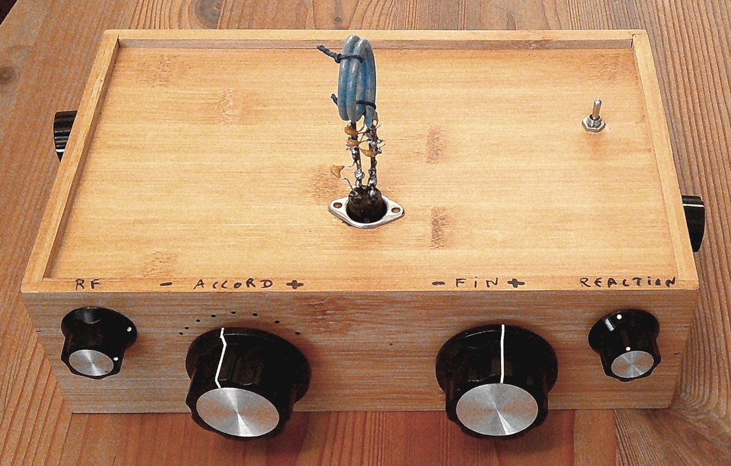

Well-designed regenerative receivers can produce spectacular results. This is a receiver that allowed me, in France, to pick up New Caledonia on 20m and Japan on 17m with a 2x10m antenna.
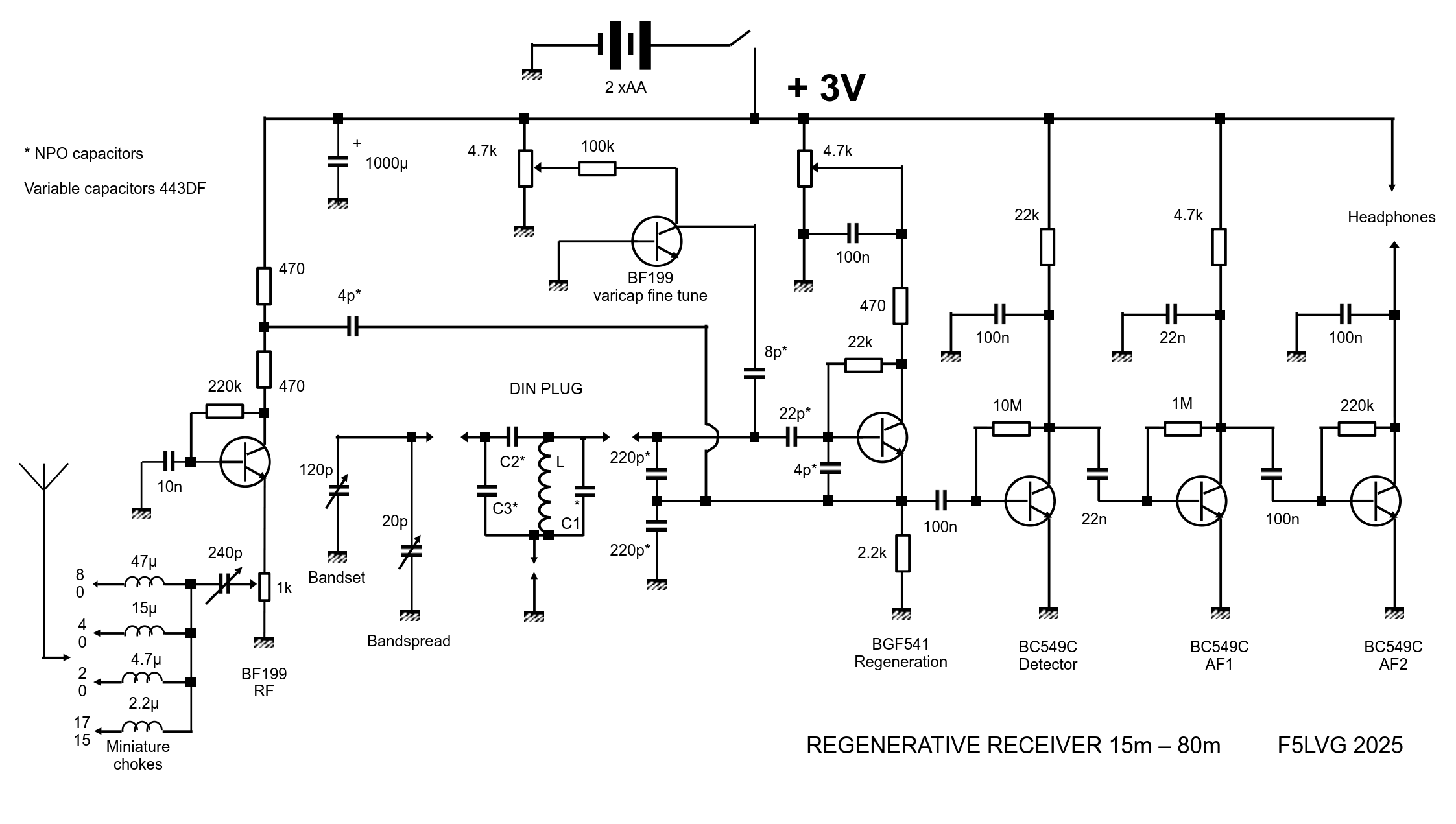
A preselector tunes the antenna to the input impedance of the RF amplifier. This amplifier is very weakly coupled to a regenerative stage (a variable-gain oscillator), which provides exceptional gain and recreates the missing carrier wave for SSB or CW demodulation. The signals are then sent to a detector stage and then two AF amplifier stages for powerful headphone listening.
The results are due to several design features:
Antenna tuning to the RF amplifier: This helps eliminate interference from powerful stations operating on a harmonic or sub-harmonic frequency.
RF stage: The presence of an RF stage virtually eliminates any interaction between the antenna and the oscillator stage.
Input attenuator: A 1k potentiometer is used to prevent the receiver from being saturated.
Original 2-transistor circuit for regeneration and detection: The first transistor (BFG541) handles both regeneration and detection. Its output is a mix of RF and AF signals. The second transistor detects the remaining RF signals and provides AF amplification for the signals already detected by the first transistor. The coupling between these two transistors must therefore allow both RF and AF signals to pass through.
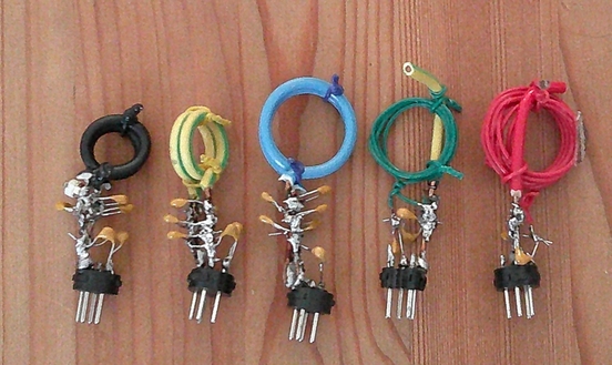
High-quality tank circuit: The circuit is designed with the lowest possible L/C ratio to favor frequency stability and selectivity. These are built on a DIN connector, so you have to change connectors to switch bands.
Frequency control: Since there is no reduction drive mechanism, tuning is done with three controls. The first variable capacitor (Bandset) covers the entire desired amateur band. A second variable capacitor (Bandspread) covers about one-sixth of the band. Finally, a transistor used as a varicap covers only one or two kHz.
Power supply: The receiver is powered by two AA batteries, which avoids much of the noise associated with using mains power.
Quality components: High-quality components are used, including NPO capacitors in the regenerative stage and a transistor with a very high transition frequency (BFG541: Ft = 9 GHz).

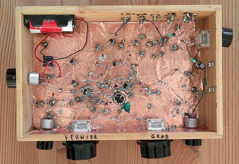
The receiver is built in a 15 x 25 cm wooden box. The interior is lined with 5-cm-wide adhesive copper strips. 10 MΩ resistors serve as connection points where needed. A 4 pF capacitor between the emitter and base of the BFG541 prevents the reception of UHF and SHF data transmissions (phone, Wi-Fi, etc.).
The BFG541 is an SMD transistor. It's easy to convert it into a conventional component. The collector pad is relatively large (3.1 mm). The transistor is attached to a flat surface with a bit of adhesive putty. The leads of two 10 MΩ, 1/4 or 1/8 W resistors are twisted together and soldered to the collector pad. The free lead of each resistor is then soldered to either the base or the emitter of the transistor. This gives you relatively long leads.
A 2.5 x 25 mm metal screw is screwed into the central shaft of the variable capacitors to easily attach a control knob. The knobs must be large due to the lack of a reduction mechanism (MFA05). The variable capacitors are directly glued to the box with cyanoacrylate (super glue). Their trimmers should be set to minimum before being secured.
The air-wound coils are built without a support. The wire used is 24AWG UL1007 solid-core hookup wire (for 40/80m) or 2.5 mm▓ (14 AWG) installation wire (for 15/17/20m). The turns are held tight with two small wires at the top and bottom of the coil. The coils made with 24AWG wire are attached to a 20A installation wire that acts as a support. Once the tuning is finished, a bit of super glue is applied to each coil to ensure sufficient mechanical rigidity. These coils, along with capacitors C1, C2, and C3, are attached directly to the base of a 4-pin DIN plug.
Band |
Turns |
Diameter |
Wire |
C1 pF |
C2 pF |
C3 pF |
80m |
10 |
20mm |
24 AWG |
487pF |
short-circuit |
- |
40m |
5 |
20mm |
24 AWG |
430 pF |
100pF |
- |
20m |
2 |
20mm |
2.5mm▓ |
676 pF |
100pF |
- |
17m |
2 |
12mm |
2.5mm▓ |
760 pF |
100pF |
100pF |
15m |
2 |
10mm |
2.5mm▓ |
537 pF |
100pF |
100pF |
All capacitors are NPO multilayer ceramics. C1 consists of 2 to 4 capacitors in parallel, each not exceeding 220pF, to obtain the desired value. The value shown is indicative only; the exact value will depend on the specific realization/construction of each coil.

